leto
Junior Member level 1

Hi,
I have a question about how can i set the output current level to the IC TB6560. According the datasheet (paragraph below) it seems to be easy. So, as I need a current of 3A I should achieve an external resistor of aprox.- 0.16 ohms or six 1 ohms resistors in parallel on NFA and NFB.
TB6560 datasheet paragraph
...The resistance of NFA terminal (RNFA) and that of NFB terminal (RNFB) determine the maximum current of phase A and B.
The reference current for the constant current operation should be set by the external resistance. When voltage for NFA and NFB terminals become 0.5 V or more (in case torque is 100 %.), it stops charging and the current which is over the reference value does not flow. Iout (A) = 0.5 V/RNF (Ω)
Example: When the maximum current is 1 A, external resistance is 0.5 Ω....
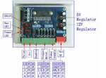
¿does anyone can take a look the attached image and tell me how it could achieve 4 levels of current (1.5 / 2.5 / 3 and 3.5 A) with one dip switch and just a couple of "visible" resistors ? I mean, do you see any other manner to do that without parallel resistors ?
Thank you.
