Continue to Site

Welcome to EDAboard.com

Welcome to our site! EDAboard.com is an international Electronics Discussion Forum focused on EDA software, circuits, schematics, books, theory, papers, asic, pld, 8051, DSP, Network, RF, Analog Design, PCB, Service Manuals... and a whole lot more! To participate you need to register. Registration is free. Click here to register now.

question about RC circuit response to periodic step voltage

Status
Not open for further replies.

perchick

Newbie level 5
Newbie level 5
Joined
Oct 23, 2012
Messages
8
Helped
0
Reputation
0
Reaction score
0
Trophy points
1,281
Activity points
1,382
hello.
im new here, so hope this is the right place for this type of questions.
its a pretty easy question but i cant seem to get to the answer. lets say i generate 5 volt step function with duty cycle of 50% in an RC circuit and im measuring the voltage on the capacitor. lets say that the frequency is high (T/2<<τ) the capacitor will charge for T/2s and discharge for the rest T/2s. here's my problem: after a while the voltage on the capacitor will stabilize on 2.5V. why is that? the function for charging and discharging is the same, so why is that the capacitor stands on 1/2 of my amplitude after a while? it seems that the capacitor is charging faster then hes discharging?
as i understand for T/2<<τ the function thats describes the voltage on the capacitor is Vc=1/RC*∫Vin*dt so when t-->0 i should get Vc-->0. I have no idea where is my problem. I hope you can explain what im doing wrong
 

Vc=1/RC*∫Vin*dt so when t-->0 i should get Vc-->0
No. When t -->0, Vc converges to initial value of Vc, which can be any voltage, according to integrator nature.

The charge equation is neither correct, it should contain ∫(Vin-Vc)dt. You better write down the exact charge and discharge differential equations and solve it.
Or refer to a simple visual explanation. For short periods, the RC circuit is just averaging the input voltage. So it's rather obvious, that the output must be duty cyle*5V.
 

thank you for the response but i steal dont get it
why the RC circuit averaging the input? why is the charge on the capacitor overall is increasing?
in the first step the charge on the capacitor increasing. when we get to T/2 the current in the opposite direction stars for T/2 sec time. the discharge rate is the same as the charging rate so i dont get why is there charge left in the capacitor after one T and increasing every T. does this have anything to do with time delay? or something called capacity memory (i have no idea what that mean)? i thought that for some reason there's charge left for a short time on the resistor and that will explain everything because there will be a short time where the resistor will have higher potential then the capacitor so eventually the charges on the both capacitor and resistor should be equal and it will explain also why it takes a while to get there.
hope you can help me, im driving myself crazy with this
 

when we get to T/2 the current in the opposite direction stars for T/2 sec time. the discharge rate is the same as the charging rate.
You didn't calculate the circuit behaviour, or calculated it wrong.

The rates are not the same, the charge rate dV/dt is proprortional to the resistor current respectively the difference between input voltage and capacitor voltage. This causes an exponential voltage waveform and makes the (average) capacitor voltage converge to the average input voltage.

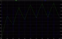
P.S.: The capacitor voltage and resistor current (=rate dV/dt) waveform are shown below. You'll see how the rate is varying.

 
Last edited:

thank you, i think I got it. if you can tell me if I got that right ill be a very happy student:
the current flows through the resistor to the capacitor until we get to half cycle. the the capacitor starts to discharge in a lower current (lower potential then the source) which starts to flow back through the resistor. at the end of each cycle there will be more charge building up on the capacitor until we reach steady state where the current from the source which charging the capacitor is equal to the current of the capacitor's discharges. in other words, the potential on the capacitor will equal on average to the potential of the source.
please tell me I got that right... i cant drop it and i need to study for other subjects and i cant do that until ill get this.

by the why, i cant seem to get to the right formula for the charge and discharge. the charge rate is Vs(1-exp(-t/τ) and discharge is Vs[(1-exp(-t/τ)]exp(-t/τ) so for infinity time the formula for Vout will be: Vout=Vs(1-exp(-t/τ){1+(1-exp(-t/τ)+[(1-exp(-t/τ)]^2+[(1-exp(-t/τ)]^3+...} thats can't be right but for some reason i cant find my mistake
 

Your charge and discharge equations are only valid for specific initial conditions.

The charge equation Vc(t) = Vs(1-exp(-t/τ)) starts at t=0 with Vc = 0. This is only the case for the first cycle, each succeeding cycle starts somewhere in the middle of charge waveform.

The discharge equation isn't correct, it's simply Vc(t) = Vc(0)*exp(-t/τ). The initial condition will be different for each cycle until steady state is reached.
 

perchick,

Yes, each energizing and de-energizing cycle starts with a different set of initial conditions until final conditions are reached. Shown in the attachment is a plot made by calculating the capacitor voltage with a periodic Laplace transform, using a period of 1 sec and an RC time constant of 5 secs.

Ratch
 

Attachments

  • Perchick.JPG
    Perchick.JPG
    32.3 KB · Views: 83

The frequency of the input signal 2/T is very high for the ripple to become visible or the RC constant is too large.

If you continue to increase the frequency, the output will tend to be exactly 2.5V. That is because the only surviving component of the input square signal's spectrum passing through the RC filter is the DC.
 

Actually the problem arises because of the fact that the capacitor can't fully charge or fully discharge. Hence it is like exponential within an exponential signal.

Also the final value depends on the duty cycle of the pulse that you give as input and the expression is given as

\[
\huge
\\ V_{final}= (\frac{T_{on}}{T_{total}}) V_{pulse}

\]

Vpulse is the input pulse voltage
Vfinal is the final mean voltage across the capacitor
Ton is the pulse period (or ON period)
Ttotal is the total period

if Ttotal=2 Ton

then it settles at the half of the input signal

Hope this helps
 

Status
Not open for further replies.

Part and Inventory Search

Welcome to EDABoard.com

Sponsor

Back
Top