Continue to Site

Welcome to EDAboard.com

Welcome to our site! EDAboard.com is an international Electronics Discussion Forum focused on EDA software, circuits, schematics, books, theory, papers, asic, pld, 8051, DSP, Network, RF, Analog Design, PCB, Service Manuals... and a whole lot more! To participate you need to register. Registration is free. Click here to register now.

Question about differentional pair opamp functioning

Status
Not open for further replies.

zeerum

Junior Member level 3
Joined
Nov 26, 2006
Messages
27
Helped
2
Reputation
4
Reaction score
1
Trophy points
1,283
Activity points
1,481
guys i need your help. i tried googling it and looked it up in books too but couldnt find an asnwer
if we take op amp as two BJTs connected, then how do we get Vo1 out of phase with the input voltage andVo2 inphase with the input. both are the same BJTs then how is it possible
please help me
 

simple explanation op amp

zeerum,
Your question is not clearly stated. Are you referring to two cascaded BJT stages, or a single differential pair, or something else. A circuit diagram would help clarify.
Regards,
Kral
 

Re: op amp basics

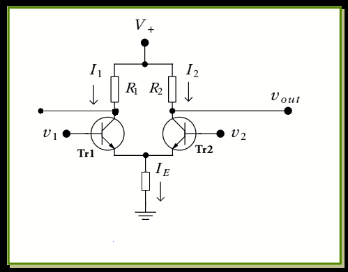
hope it would help making my query more clear. all i want to know is how come output from one transistor is in phase with the input signal and out of phase from the other transistor


92_1226159419.gif
 

Re: op amp basics

zeerum,
Suppose v1 and V2 are equal positive voltages. If v1 increases, the current through R1 increases, causing the collector voltage to decrease (out of phase output at the Tr1 collector). At the same time, the emitter voltage on both transistors increases due to the increase in emitter current thru Tr1. The result is that the base-emitter voltage of Tr2 is lower (less positive) than it was, causing the collector current thru Tr2 to decrease. This results in an increase in vout (in phase with the input).
Regards,
Kral
 

Re: op amp basics

Hey, what you are asking it is not possible.

The circuit you are studing is the differentian pair.
There are two modes of operation of this amplifier: common mode input and diferential mode input.
The first common mode input is when you put the same signa in both inputs, and in this case there is no input or a very small one.
The second case is when you are using a differential input, that is, not referenced to ground. Other form to see that is conecting one output of the source to one input of the circuit and the other output to the other input, as I show with V1 in the graph. But it is confusing, a better way to figure it out is an equivalent circuit that I use with V2 and V3. This is the differential mode and there is amplification. For Q1 and Q2 the voltage in their collectors are 180º with respect to their inputs and both inputs are 180º between them.
 

Re: op amp basics

Hi zeerum,

here is a rather simple explanation:

Assume that v1 is your input and v2 is grounded.
Then, T1 operates as a common emitter stage (inverting at its output).
T2 gets an input signal via the common emitter node and it operates as a common base stage (non-inverting at its output). That´s the whole secret.
Regards
 

Re: op amp basics

LvW said:
Hi zeerum,

here is a rather simple explanation:

Assume that v1 is your input and v2 is grounded.
Then, T1 operates as a common emitter stage (inverting at its output).
T2 gets an input signal via the common emitter node and it operates as a common base stage (non-inverting at its output). That´s the whole secret.
Regards
i didn't understand how T2 acts as a common base amplifier.
 

Re: op amp basics

desperado1 said:
i didn't understand how T2 acts as a common base amplifier.

T2 receives its input signal at the emitter node, right ?
And its base is grounded. The output is at the collector node of T2.
That´s the definition of common base operation of a BJT (in this case T2).
It´s clear now ?

More than that, the same applies for T1 if you exchange the input signals.
And now - as it is a linear device - you may excite the amplifier at the same time with BOTH input voltages, and the rule of superposition applies leading to the known behaviour of a diff. amp.
 

Re: op amp basics

dear zerrum

the best way to be more convinced is to refer to Dr. Razavi's CMOS Electronics Book. there you can find the more dicriptive text of this phenomenon.

best regards
 

Hi.............
I read above threads!.....

I have a basic doubt.......

how common emitter amplifier produce 180 phase shift in output?
 

Hi.............
I read above threads!.....

I have a basic doubt.......

how common emitter amplifier produce 180 phase shift in output?

See my 8-11-8 post. An increasing base voltage results in an increasing base current. This causes an increased voltage drop across the collector resistor and a decreasing collector voltage.
Regards
Kral
 

See my 8-11-8 post. An increasing base voltage results in an increasing base current. This causes an increased voltage drop across the collector resistor and a decreasing collector voltage.
Regards
Kral

More correct: An increasing base voltage results (drop the middle part) in an increased voltage drop across the collector resistor and a decreasing collector voltage.
(Note that the BJT is a voltage-controlled element).
 
Last edited:

Status
Not open for further replies.

Part and Inventory Search

Welcome to EDABoard.com

Sponsor

Back
Top