Continue to Site

Welcome to EDAboard.com

Welcome to our site! EDAboard.com is an international Electronics Discussion Forum focused on EDA software, circuits, schematics, books, theory, papers, asic, pld, 8051, DSP, Network, RF, Analog Design, PCB, Service Manuals... and a whole lot more! To participate you need to register. Registration is free. Click here to register now.

Quectel GSM Module Microphone Noise And Gain Problem

Status
Not open for further replies.

nihan_A

Newbie level 5
Newbie level 5
Joined
Apr 11, 2018
Messages
8
Helped
1
Reputation
2
Reaction score
0
Trophy points
1
Activity points
131
Hello

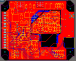
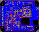
I work on an Emergency call project which makes people be enable to communicate with a call center in an emergency case. I uploaded my PCB and schematic.
In the schematic Mic Amplifier Ts971 is supplied by Vcc 3.3V but since I noticed I was trying to amplify it more than it was capable of so I supplied it by 3.8V Vcc and I did not had any problem when I check signals by oscilloscope before I connected GSM module. After I connected GSM module I noticed there is noise heard from the other side of the phone with a low speaking audio. And if I increase gain of the amplifier circuit to hear the speaking there won't be any speaking sound but just noise. As you can see on the PCB there is analog and digital ground planes and filter capacitors. I don't know if I discribed the problem exactly but what else can I do to prevent the noise?
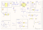
schematic.png

top.png

bottom.png
 

Hi,

Maybe this causes the problem. maybe not:
But I personally don`t lke the huge GND-loop you generated. It will act as an antenna. Sending and receiving.
I´d make a cut at the top right corner. (in detail it depends on the HF signals involved in this "cut" area). As well a in blue as in red layer.

KLaus
 

Hello Klaus,

Thanks for reply, I cut the board just like you said but it seems that is not the problem cause nothing has changed. When I don't use mic amplifier circuit and directly connect microphone to GSM module there is not any problem. So I think problem is because of the amplifier circuit but when I connect amplifier circuit from another board to this board it works well, there is still noise but voice gets amplified. I think GSM module somehow effects the amplifier circuit..
 

Hi,
"FB1" seems to be then join point if the two GND planes analog and digital.
It is very close to the feedback path of the Mic amplifier.
At this point it just connects the blue layer, which is GND, but split..
--> this placement is not ideal in regards of microphone noise.
--> additionally I'd expect a couple of vias to connect red and blue GND on both sides next to FB1.

Klaus
 

Thank you.

I will consider your advices and redesign my PCB.
 

Hi,

If redesign:
Then I´d add an input filter at the ampifier, just to reduce input bandwidth and avoid amplifier ringing.
A series R may be sufficient in simplest case.

***
I know many designers use the true GND_plane (red) in combination with the copper pour (blue).
I´m no fried of this, because the copper pour is not much better than single wires.
--> It´s far better to not use copper pour but use short GND wires to vias to the true GND_plane.

You simply can use your layout and follow the signal paths and their associated GNG_return_path.
Sometimes the return paths are more lengthy than the signal paths and enclose a big area, which is a measure for EMI/EMC antenna function (transmitting as well as receiving)

Klaus
 

Status
Not open for further replies.

Part and Inventory Search

Welcome to EDABoard.com

Sponsor

Back
Top