- Joined
- Jan 22, 2008
- Messages
- 53,721
- Helped
- 14,812
- Reputation
- 29,921
- Reaction score
- 14,450
- Trophy points
- 1,393
- Location
- Bochum, Germany
- Activity points
- 303,698

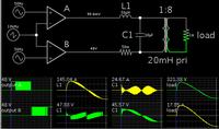
I presume Falstad doesn't use a saturable core in the standard transformer model (other circuit simulators do neither, and it's always a bit demanding to find the right core parameters if you use such a model).On the other hand, if you start the SPWM at the 90 or 270 degree mark, then you expose all components to peak current abruptly.

So yes, a voltage ramp is probably the most simple solution. Alternatively, a fast saturation free start could use one halfwave of 50% magnitude and switch to 100% after the first zero crossing.


Hi guys,
I've just built a pure sinewave inverter (230V / 3kW) with a LF output transformer but I want to change the regular (EI) transformer with a real(!) one - a high efficiency toroidal type.
Anyway, EI transformers have air gaps so their iron losses are significant. I really wonder how your transformer has such a small idle consumption - it must be a masterpiece.
As far as i read, EI transformers used in UPS/inverters have lousy windings (on purpose) to use their leakage inductance as a low pass filter (together with the output capacitor).
My current toroidal transformer costs me almost 450 EUR (btw, I live in Europe) so I hope it's really worth the money. Being used by Xantrex in their high-end design it's a good news.
My battery string has over 1 kA starting current so that may be a problem.
About high frequency filtering.. isn't a toroid inductance (choke) in series with the primary winding a solutions, as discussed before? And the capacitor might be eventually located across the secondary?
" We always use M6 laminations, but when we have asked for sample transformers from a possible new vendor in the far east, they sometimes try to pass off M19 or worse in the sample."
I have had the opposite problem. For validation and certification, they provide a transformer with the optimal materials.
Once that the product has been validated and certified, and actual production shipments start, they start to degrade the transformer...slowly. For instance, they'll reduce the copper half an AWG gage. They will start interleaving M19 material with M6 material. If you don't notice the incremental degradation, they will continue the practice until there is a complaint, at which point they'll back off.
Some of them are actually quite smart in their cheating. Once we had a transformer with higher DCR. First suspicion: the wire gage. Careful measurement with an optical comparator yielded spot-on wire diameter. Disassembling the transformer yielded almost identical wire length of a good transformer.
We were going crazy until someone suggested a chemical analysis of the wire itself. Electrical grade copper is 99.9% pure, as any impurities quickly degrade conductivity. Refining copper to such purity is a significant cost increase.
Turns out they were using 98% pure copper. Clever, very clever the way the cheat.
Is this a value you've actually measured, or is it a manufacturer's spec?
I see no advantage to using an inductor on the primary side. It has to carry a much higher current than secondary side current would be, and unless special wire (litz) is used, proximity effect losses are likely to be high. Why not use a secondary side inductor? The capacitor should be located on the secondary.
Currently, the local inverter folks provide a "low idle kit" consisting of a small saturable toroid with the primary making a single turn through the toroid, but this doesn't do anything as soon as much load is applied.
We use cookies and similar technologies for the following purposes:
Do you accept cookies and these technologies?
We use cookies and similar technologies for the following purposes:
Do you accept cookies and these technologies?
