R
red_alert
Guest

Hi guys,
I've just built a pure sinewave inverter (230V / 3kW) with a LF output transformer but I want to change the regular (EI) transformer with a real(!) one - a high efficiency toroidal type.
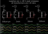
But here comes the problem: the traditional inverter design use the output LF transformer leakage inductance as a "natural" filter for the SPWM high frequency band.
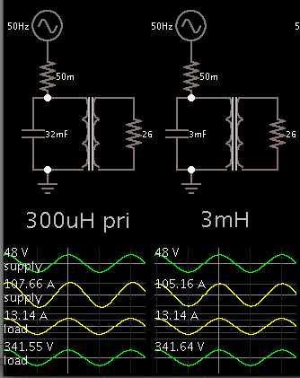
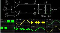
The toroidal transformer has a very low leakage inductance so I have to design a separate filter between the H-bridge output and toroidal transformer input (30V AC, being used with a 48V DC solar system).
The (s)PWM frequency it's about 10 kHz. The H-bridge max output current will be 75 A. How to properly design a filter for this situation? It has to be a LC filter (with C parallel mounted on the transformer input)?
Like I said before, the actual design uses the transformer's leakage inductance and a parallel capacitor (2.2 uF) across the transformer output (230V).
Another problem I've encountered is the toroidal transformer inrush current at startup so I
have to find a way to limit it. Being a high current (>100A) I couldn't use NTC resitors and I want to avoid using relays (to shunt an inline high-watt resistor) too.
I guess the solution is to design a software soft-start.. so it means I have to generate a progresivelly increasing amplitude of the SPWM sinewave, during one second or so at startup? Do I have to disconnect the load (230V) during this startup sequence?
Thank you in advance for any tips.


