[SOLVED] Pure Sine wave Extraction

Status
Not open for further replies.

Debdut

Full Member level 3
Full Member level 3
Joined
Oct 29, 2013
Messages
174
Helped
7
Reputation
14
Reaction score
7
Trophy points
1,298
Activity points
2,575
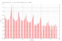
I am designing a Ring Oscillator with oscillation frequency of 388 MHz. The output signal of the oscillator is not a pure sine wave. How can I extract the pure 388 MHz sinusoidal signal from the crowd of all the frequencies.

Below is a image showing the DFT of the output signal (simulated in Cadence)
 

I guess you need to filter the output. A high Q filter will boost the 388MHz fundamental as well as reducing the harmonics, allowing you to get a cleaner output for the same order filter.

Another way to reduce the distortion is to add the outputs from more than 1 of the inverters. E.g. if you have 5 inverters in the ring, you can add (or mix) the outputs from the 3'rd and 5'th inverters. This won't give a very big improvement, but it's simple and costs almost nothing.
 

Can you explain the concept of adding the outputs of the inverters ??

I have three inverter stages, what will I do?
 

If you add a square wave to a slightly delayed copy of itself, you get a staircase waveform that looks more like a sine wave. Delays up to about a quarter wave would be useul. I don't think this approach can be used if you only have three inverters, so you will need to use an analog filter.
 

Thank godfreyl for explaining !

Any tips for analog filter....
 

Maybe a simple LC filter? I don't know what the output's going to be connected to, how clean it has to be etc, so can't give any detailed recommendations.
 

Status
Not open for further replies.