Continue to Site

Welcome to EDAboard.com

Welcome to our site! EDAboard.com is an international Electronics Discussion Forum focused on EDA software, circuits, schematics, books, theory, papers, asic, pld, 8051, DSP, Network, RF, Analog Design, PCB, Service Manuals... and a whole lot more! To participate you need to register. Registration is free. Click here to register now.

Pulse Transformer Paralleling Doesn’t Add Up

AnalogTech

Newbie
Newbie level 4
Joined
Jun 12, 2024
Messages
5
Helped
0
Reputation
0
Reaction score
0
Trophy points
1
Activity points
38
Dear Friends of Electronics,

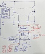
I am developing a car battery powered full-bridge DC/DC converter with a pulse transformer and so far I have managed to convert around 305 Watt on 4.4 Ohm load with good efficiency, also been able to close the feedback loop, got it stable so far so good.

The issue I can’t get my head around is that, I produced the same exact pulse transformer which also on its own delivers around the same power 305 Watt with practically identical efficiency, but upon paralleling both transformers both in terms of primaries and secondaries (both transformers have a single primary and a single secondary) I don’t get significant power increase, instead only around 80 Watt surplus for a total of 384 Watt with slightly higher efficiency than with a single transformer.

This way with single transformer upon 4.4 Ohm loading, the output drops from 45V to 36V or 305 Watt and when the two transformers are paralleled the output drops when loaded from 45V to 41V at 4.4 Ohms or 384 Watt, which is nothing around the doubling of power or the 600 Watt mark. Because the feedback loop is closed the duty cycle opens up to the maximum 42% (set up by myself) in both cases.

I want to increase the output power and I cannot understand why paralleling two power sources with identical characteristics doesn’t add up properly, does anyone have an experience with this or have any ideas what it could be?

Thanks,
Kind Regards
 
Hi,

provide a schematic where we can see both situations: with one transformer and with two.

Klaus
 
Hi,

provide a schematic where we can see both situations: with one transformer and with two.

Klaus
Hi Klaus sure, please see attached schematic:
 

Attachments

  • IMG_1489.jpeg
    IMG_1489.jpeg
    996.4 KB · Views: 108
Last edited:
My math says you want 51.4 V loaded output voltage for 600 W. As unloaded voltage is only 45 V, transformer winding ratio is apparently inappropriate.

Measurements suggest nevertheless that transformer series impedance (leakage inductance + winding resistance) is too high.

The basic behaviour as described in question title is just expectable.
 
Hi,

from what I see and understand ... the only thing that is wrong is your expectation. (technically seen. Not in the meaning to offend you)

*
Example:

let´s say you have a perfect 10V power supply and a 10 Ohms load
Connect both. The load sees 10V, this causes 1A and thus 10W

Now if you connect a second 10V power supply in parallel, then still the load sees 10V, causing again 1A and 10W.

If you expect the 10 Ohms load to produce 20W (double than before), then the load needs to get 14.14V.
14.14V causes 1.414A and thus 20W.

--> you need to increase the voltage at the load to generate higher power.

To increase the voltage ... one might assume that connecting the power supplies (secondaries) in series will work. Let´s see:
By connecting the power supplies (secondaries) in series you get 10V +10V = 20V at the load.
This causes 2A and thus 40W. Again not the expected 20W.

--> now what could be the solution to your problem?
There are several ... some may fit your needs, some not. (You have to tell us your requirements).

So one solution may be not to only use an additional transformer, but also an additional rectifier and load.

*******
Generally for a single load:
Ohm´s law is true: I = V / R
and also P = V x I ... or both combined: P = V x V / R = V^2 / R

It does not matter where the voltage comes from ... you have to focus on the voltage across the load.

********
Back to your circuit:
There is a voltage feedback .. and a control part.
What´s the use of it? How does it work?
If there is such a voltage control loop, I expect it to keep the voltage constant.
For example it is used to keep your output voltage at 40V:
Then
* on no load condition .. (where in your case you get 45V) it reduces the duty cycle to maintain 40V
* with load .. (where in your case you get 36V) it increases the duty cycle to again maintain 40V
Why does it not work this way?

*****
Back to the formula: P = V^2 / R.
If you want to double the power then you have 2 options:
* increase the voltage by a factor of SQRT(2), --> 10V x SQRT(2) = 14.14V, or
* divide the load resistance by 2 --> 4.4 Ohms / 2 = 2.2 Ohms

Klaus
 
Dear Klaus,

About the expectation I have only followed the experiment and because needed more power on the 4.4 Ohms I lowered the output impedance of the power supply by means of getting a 2nd identical trafo (capable on its own do deliver the same power around 304W) and paralleling of the secondaries (and the primaries).

Yes feedback loop keeps the output voltage constant, with no load the PWM is only 2-3% and with increasing loads it goes up and follows up with the high demands, it goes to max when output cannot be sustained i.e. with high output power. No jitters and no phase shifts, it took me some time to get here :) Efficiency is also above 80% which is a good sign also. Only need to figure out the scaling up of multiple transformers and why the scaling so far didnt work..

Kind regards,
Martin
 
Last edited:
Hi,

your circuit works as expected.

But your regulation look does not work. It obviously does not keep voltage constant.

In case of one transformer the drop from zero load to 4.4 Ohm load is 45V - 36V = 9V
In case of two transformers the drop is from 45V to 41V = 4V
This indicates that the output impedance is about 0.5 as before. But half the output impedance does not mean double the output power.

I´ve already given the formulae. Do your math.

Klaus
 
Hi,

your circuit works as expected.
i have no expectations, I only observe and adjust.
But your regulation look does not work. It obviously does not keep voltage constant.
Yes it does, but as with every other real power supply out there the moment comes where the load is too much and the supply goes out of regulation where the nominal output voltage drops, you cannot load a power supply indefinitely.
In case of one transformer the drop from zero load to 4.4 Ohm load is 45V - 36V = 9V
In case of two transformers the drop is from 45V to 41V = 4V
This indicates that the output impedance is about 0.5 as before. But half the output impedance does not mean double the output power.

I hear you here with the 0.5 Ohm, it is 0.43 yes! This with the output impedance is also true.
I´ve already given the formulae. Do your math.

Klaus
I have to respectfully disagree with some things and agree with other. Please see in blue above

My math says you want 51.4 V loaded output voltage for 600 W. As unloaded voltage is only 45 V, transformer winding ratio is apparently inappropriate.

Measurements suggest nevertheless that transformer series impedance (leakage inductance + winding resistance) is too high.

The basic behaviour as described in question title is just expectable.

Thank you FvM for jumping in and your thoughts. You are right with the with the 51.4V yes! The ratio of the trafo is in accordance with the desired output voltage: 4:16 turns for 13V input and 45V output. I have tried also lower counts with 2:8 and 3:12 where I reach higher voltages under 4.4 Ohm load but loose efficiency. I am trying to squeeze as much efficient power out of the 2 ferrite cores I have as possible. Something else is going on here and I think I know what it is.
 
I'd start with a complete transformer characterization (main and leakage inductance, winding resistance) and check voltage drop in a simulation.
 

LaTeX Commands Quick-Menu:

Similar threads

Part and Inventory Search

Welcome to EDABoard.com

Sponsor

Back
Top