Continue to Site

Welcome to EDAboard.com

Welcome to our site! EDAboard.com is an international Electronics Discussion Forum focused on EDA software, circuits, schematics, books, theory, papers, asic, pld, 8051, DSP, Network, RF, Analog Design, PCB, Service Manuals... and a whole lot more! To participate you need to register. Registration is free. Click here to register now.

Pulse shortening circuit

Status
Not open for further replies.

jbeniston

Advanced Member level 1
Joined
May 5, 2005
Messages
460
Helped
106
Reputation
214
Reaction score
73
Trophy points
1,308
Activity points
3,494
Does anyone have any recommendations for a low-power pulse shortening circuit?

i.e. I have an incoming clock pulse and I would like to reduce the duty cycle by a rough amount.
 

Does anyone have any recommendations for a low-power pulse shortening circuit?
i.e. I have an incoming clock pulse and I would like to reduce the duty cycle by a rough amount.
Depending on the minimum width of the output pulse, you can consider 555 timer, TTL 74121, CMOC 4528,etc ..
:wink:
IanP
 

Depending on the minimum width of the output pulse, you can consider 555 timer, TTL 74121, CMOC 4528,etc ..
:wink:
IanP
Thanks. I should have said CMOS circuit.
 

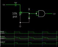
By putting a capacitor in series, it will create a ramp wave. Send it to a logic gate. The output pulse is shortened.

The percent reduction can be adjusted by use of a potentiometer.

Sample schematic:


The percent reduction can be adjusted by use of a potentiometer.

Sample schematic:


Hi, i have a doubt...

How can we reduce the amplitude by this potentiometer....

By using this cap we can change the width of the output pulse... am i rite?...

thanks,,,,,,
 

Do you want it to use in welding machine? Pulse welding type?

If not, I guess you just want to change the width of your signal. If this true, then use micro-controllers to reduce the width. And if you need to change just the amplitude, just use a POT.


Hi, i have a doubt...

How can we reduce the amplitude by this potentiometer....

Do you mean the voltage amplitude? That is determined by the supply voltage to the logic gate.

By using this cap we can change the width of the output pulse... am i rite?...

thanks,,,,,,

Yes, if you choose the Farad value (together with the pot value) properly. Together they need to produce a suitable time constant, which will respond within the incoming pulse length.

My schematic shows typical values that will work with 1 kHz.

If your frequency of operation is higher, then reduce the Farad value.
If lower, then increase it.

The potentiometer provides adjustment of the output pulse length. It ranges from zero to about 90 percent of incoming pulse length.
 
Thanks, and yeah, time constant.. absolutely...

So its a kind of PWM circuit am i right..
 

Status
Not open for further replies.

Part and Inventory Search

Welcome to EDABoard.com

Sponsor

Back
Top