Vermes
Advanced Member level 4


It is a design of mobile pulse sensor. The measuring system consists of the following elements:
- sensor with the filters and amplifier
- Atmega8A (housing PDIP) – digital conversion
- BTM-222 module – transmission using Bluetooth interface
- receiving stations: laptop with program in LabVIEW, smartphone with Android application
The system allows you to measure human pulse and transmit the PPG (photoplethysmography) wave and display the result in real time. The range of the device is about 25m.
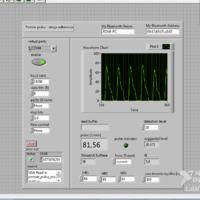
Receving program panel during entering the measurements:

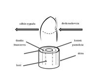
The sensor is to be placed on a finger and it looks like that:


List of the components used (according to the diagram):
- LM358N – amplifier LM358N
- T1 – phototransistor L-932P3C
- LED3 – IR LED L-934F3BT
- R2, R10 – adjustable resistor 1Mohm
- R1 – resistor 300ohm
- R3, R9 – resistors 1Mohm
- R7 – 10kohm
- R8 – 18kohm
- C6, C8 – electrolytic capacitor 1uF 50V
- C9 – 330nF
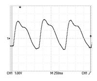
IR LED emits 940 nm wavelength. After passing through the pulsating tissue, light controls the gate of phototransistor. Then noise and constant component are removed from the signal. The last stage consists of the amplification of the signal and thus the result is as shown below:

The sensor should be protected against the influence of external conditions such as IR waves produced by Sun. To make this, you can use for example a piece of black fabric.
Another important issue is that you have to make sure that the buckle is stable enough. The sensor should not move on the finger.
Strengthening and sensitivity of the transistor can be controlled by manipulating the value of the adjustable resistors. You should obtain the amplitude of the output signal not greater than 5V, which is subjected to a tolerance of the A/C converter of Atmega.
Link to original thread (useful attachment) - Czujnik pulsu człowieka z transmisją danych Bluetooth