yefj
Advanced Member level 5

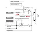
Hello, In the photo bellow there is a diagram for general purpose input output(GPIO).
When they say in the manual "The following code configures pin 5 from Port C as a digital input with pull-up and filter"
We see in the diagram is just connecting the output to VDD and pull down is connecting the output to GND.
So if we have digital input of a square wave then the pull up cancels it totally because we have path to VDD (OR) ground.
We ruin our signal by doing pullup or pull down.
What is it good for?
Thanks

