Pull and Pull down resistors

Status
Not open for further replies.

snaku

Junior Member level 3
Joined
Oct 5, 2010
Messages
27
Helped
1
Reputation
2
Reaction score
1
Trophy points
1,293
Location
Bangalore
Activity points
1,448
Pull up and Pull down resistors

Could you please suggest me some practical circuits having pull-up and pull-down resistors, to understand this concept well?
 

Hi,

Usually they are used at the input stage. They can be needed in the output stage when the device can not both sink and source current. eg In SG3524, it can either sink or source current, but can not do both, so you need to connect pull-ups or pull-downs at the output.

But usually, they are used at the input stage. Let's take an example. Say you have a microcontroller pin connected to a switch which is in turn connected to +5V. When the switch is closed, the pin receives +5v. However if the switch is open, the switch receives no input, it's not high or low, it's just a high-impedance (high-Z) input state, which can not be made use of in the code. So, you connect a pull-down resistor from the pin to ground, so that when the switch is open, the microcontroller pin is 0 - connected to ground.
Other applications maybe in communication, eg. I2C, etc, or converters, eg. ADC, DAC, etc.

Hope this helps.
Tahmid.

---------- Post added at 08:57 ---------- Previous post was at 08:51 ----------

Hi,

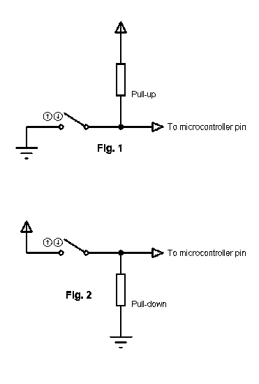
This should clear things:


In fig.1 the switch can only sink current, but when it is open, the pin is floating and this is unwanted. Here the pull-up sources current by pulling the pin upto a logic high.
In fig.2 the switch can only source current, but when it is open, the pin is floating and the pull-down sinks current by pulling the pin to a logic low.

Hope this helps.
Tahmid.
 
Reactions: snaku

    snaku

    Points: 2
    Helpful Answer Positive Rating
which fig????? i think it is not attached.

Simplest example can be your controller which has pull up internally or it is given externally.
Port pins cannot supply much current to externally interfaced device. If it cannot drive the external component, then it loads the controller pins and may damage it. So in order to drive the external devices, we use pull up resistor ( 1 end to port pin & other end to VCC) and follow kirchoff's current law. So when you apply voltage to resistor there is flow of current and as by KCL the current at a node adds up , the current from port pin and current from pull up adds up and then moves to interfaced module and drives it.
Sometimes the module require more current to be driven which cannot be achieved by pull up, then we go for IC based current amplifiers for that purpose.
 

The figure posted here: (I didn't attach it.)


Hope this helps.
Tahmid.
 
Reactions: snaku

    snaku

    Points: 2
    Helpful Answer Positive Rating
As the port pin is driven to a high impedance state by using the power supply with a resistor,the resistor is called PULL UP resistor. If the resistor is connected to the ground from the port pin that resistor is called Pull down resistor. It creates a low impedance state @ the port pin to which it is connected.
Regards,
Jerin.
 

Status
Not open for further replies.

Similar threads

Cookies are required to use this site. You must accept them to continue using the site. Learn more…