The_JinJ
Newbie level 3

Hi all ")
I'm trying to program a PIC18F2550 with a custom firmware.
I have tried several ways including using circuits from
**broken link removed**
http://tomeko.net/misc.php#COM84
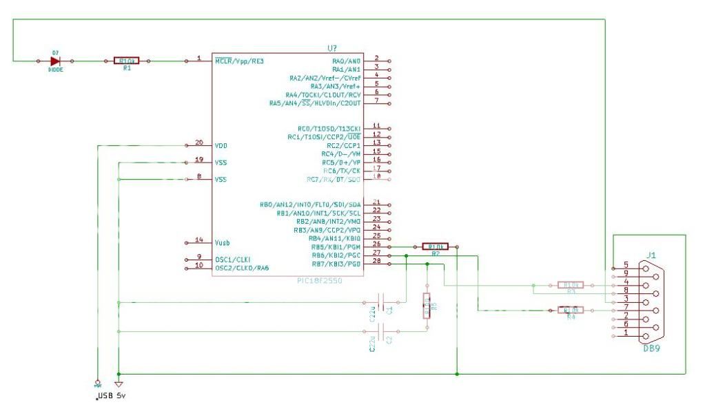
grounding the appropriate VSS pins, tried adding caps to pin 27 & 28.
I've tried both low and high voltage programming with no success - Winpic seems to read the chip (I get 00ffff back when read and all 0's if no power or serial connection)
Winpic gives the following messages:
The fuses are set correctly although I don't think I could write them anyway!
When doing high voltage programming I have 10.55v on pin 1 which should be enough to enter programming mode. Pin 26 in pulled to griound to make sure it stays out of low voltage programming mode.
I have tried this with 2 PICs so don't think they are faulty.
Any pointers where to go next (sorry if I have missed any required info)
I'm trying to program a PIC18F2550 with a custom firmware.
I have tried several ways including using circuits from
**broken link removed**
http://tomeko.net/misc.php#COM84
grounding the appropriate VSS pins, tried adding caps to pin 27 & 28.
I've tried both low and high voltage programming with no success - Winpic seems to read the chip (I get 00ffff back when read and all 0's if no power or serial connection)
Winpic gives the following messages:
Code:
Info: Loading definitions for "PIC18F2550" from C:\Program Files\WinPic\devices.ini .
Info: Support for some newer PIC18F devices added by Martin v.d. Werff 2005
Parsed "C:\Program Files\WinPic\MPLAB\MPLAB IDE\Device\PIC18F2550.dev" : found 113 bit combinations in 39 configuration bit groups .
PIC18F: family='21'=4550, WriteLatch=32 bytes, EraseLatch=64 bytes .
Initialising PIC-Programmer: Success.
Testing: delay(500ms) took 0.50 seconds, timer_freq=2994.9300 MHz ... ok
Results from LoadHex: LastProgAdr=0x001692 LastDataAdr=0xEFFFFF (C:\Documents and Settings\pic18f2550usb.hex)
Programming...
Erasing ("bulk" or "chip") ...
Erasing chip using algorithm "PIC18F" .
Programming CODE, 0x000000..0x001692
Verifying CODE, 0x000000..0x001692
Verifying 0x000000..0x001692
Verify Error: 000000: read 00FFFF, wanted 00EF30, mask 00FFFF  ==> diff=0010CF
Verify Error: 000002: read 00FFFF, wanted 00F00B, mask 00FFFF  ==> diff=000FF4
Verify Error: 000004: read 00FFFF, wanted 000012, mask 00FFFF  ==> diff=00FFED
Verify Error: 000006: read 00FFFF, wanted 000012, mask 00FFFF  ==> diff=00FFED
More Verify Errors, unable to list all (total=2890)
Programming CONFIG, 0x300000..0x30000C
Verifying CONFIG, 0x300000..0x30000C
Verifying 0x300000..0x30000C
Verify Error: 300000: read 00FFFF, wanted 000E22, mask 00CF3F  ==> diff=00C11D
Verify Error: 300002: read 00FFFF, wanted 001E3F, mask 001F3F  ==> diff=000100
Verify Error: 300004: read 00FFFF, wanted 0081FF, mask 008700  ==> diff=000600
Verify Error: 300006: read 00FFFF, wanted 00FF85, mask 0000E5  ==> diff=000060
ERROR: Programming FAILED !
The fuses are set correctly although I don't think I could write them anyway!
When doing high voltage programming I have 10.55v on pin 1 which should be enough to enter programming mode. Pin 26 in pulled to griound to make sure it stays out of low voltage programming mode.
I have tried this with 2 PICs so don't think they are faulty.
Any pointers where to go next (sorry if I have missed any required info)