stringskipper
Newbie level 5

- Joined
- Aug 5, 2008
- Messages
- 10
- Helped
- 0
- Reputation
- 0
- Reaction score
- 0
- Trophy points
- 1,281
- Activity points
- 1,378
Hi everybody,
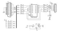
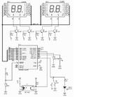
i have problem during a reprogramming ATTiny 2313. On a PORTB i've conected 7-seg display, so i'm using MISO, MOSI and SCK during a code execution. Everything works fine ONLY first time when i put down code to the microcontroller. Test code just blinks some number on 7-seg display. But when i try to change code, i get "no response" from microcontroller. I've tried to disconnect programing pins from 7-seg display, so i've put microcontroller on a diferent board, only with pins for programming and power supply, but problem is still present. Using another, "empty", microcontroller i get stuck in a same situation. First time, everything is ok, but second time there is a problem. Some how "old" program is making a trouble with SPI connection. Tried to put some pull-up's on programming lines, but nothing sucessuful. On schematic, programming pins are connected via resistor (330) to 7seg anode, which cathode is connected to collector of bjt (common emitter). If picture is needed, i will upload it, so as schematic of programmer.
- - - Updated - - -
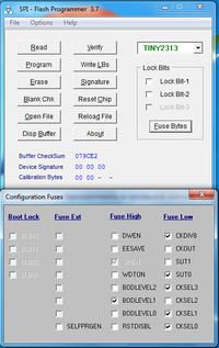
Fuse bits are correct. I'm running internal oscillator, by default.


