Continue to Site

Welcome to EDAboard.com

Welcome to our site! EDAboard.com is an international Electronics Discussion Forum focused on EDA software, circuits, schematics, books, theory, papers, asic, pld, 8051, DSP, Network, RF, Analog Design, PCB, Service Manuals... and a whole lot more! To participate you need to register. Registration is free. Click here to register now.

Problem with firing case and controlling pulses when simulating firing triac circuit

Status
Not open for further replies.

Eng.AH

Newbie level 6
Newbie level 6
Joined
Mar 24, 2010
Messages
14
Helped
0
Reputation
0
Reaction score
0
Trophy points
1,281
Location
Well, It's a good place
Activity points
1,374
Hi all,

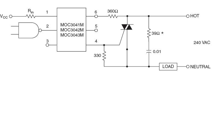
I'm trying to simulate the firing triac circuit using MOC 3041 , zero crossing opt.

well, the firing case is the main problem, then the second one is controlling that pulses using
Mikro c. (PIC16f876a
see that in att. file
I'm using proteus. I'm beginer in that sort of simulations.

If any one can help?


THANKS
 

Re: Plz Help me

Hi,

Have looked at your design, but not your code.

The circuit is really wrong, R3 is at 10k so it will never turn on the optos led.
Your AC circuit is connected to the 0v of the Pic - so you do not have any isolation !

If you search on this string, as I have just done, you will find similar circuits in this forum that should show you how to do it correctly. " proteus isis triac simulation "
 

    Eng.AH

    Points: 2
    Helpful Answer Positive Rating
Re: Plz Help me

wp100 said:
Hi,

Have looked at your design, but not your code.

The circuit is really wrong, R3 is at 10k so it will never turn on the optos led.
Your AC circuit is connected to the 0v of the Pic - so you do not have any isolation !

If you search on this string, as I have just done, you will find similar circuits in this forum that should show you how to do it correctly. " proteus isis triac simulation "

Thanks,

as a matter of fact, these are NOT the real problems. Because it's not what I work with( I'm sorry for uploading the wrong one).The really problem is:

How can I deal with MOC 3041? In other words, what is the functionality of it?

I read the data-sheet !
 

Re: Plz Help me

Hi,

The main function of the Moc3041 is to optically isolate your low voltage dc control circuit from the AC circuit.
Its other function is to drive a power triac using the zero voltage crossover method .

See this little demo for a good explanation of the circuit or again just serach this forum for the many previous theads on triac opto isolators.
**broken link removed**
 

    Eng.AH

    Points: 2
    Helpful Answer Positive Rating
Re: Plz Help me

Hi,

I watched the video.

But I have an alternative solution. i can get a sample from the Hot line say 220V. and then reduce it to a 5 V AC for synchronous purpose . that 5 V will be the input to the PIC. PIC will fire the gate's triac.


is that possible. And if so, how can be implemented ?


thanks
 

Re: Plz Help me

Hi,

It used to be quite common to do just that, take a sync signal from the mains voltage, adding a resistor, diode and zenner in circuit as well and you could also power the pic with +5v dc.

The only problem is that the whole circuit is at main potential so rather dangerous by todays standards, plus it totally defeats the use of the opto isolator / traic driver.

Try look at some of the early Microchip application notes and other places for such circuit examples; it was also common to use the 50hz mains to derive a real time clock timebase for the micros and earlier ttl circuity.
 

    Eng.AH

    Points: 2
    Helpful Answer Positive Rating
Re: Plz Help me

Thanks a lot wp100,

I found the circuit below with the datasheet.


But, I have questions here:

1. My load are 2 heaters, each 1000W. Is this circuit supports the heaters, I mean are the heaters considered as a resistive load?

2.The MOC 3041 will detect the zero -crossing, OK. But When I make LED Hi, when should the internal triac conducts. Well, I cannot understand the way of it. suppose the LED Hi when the main voltage at a certain time at say, 100 v and at that point LED goes hi, and then goes down. what will be the result. the zero croosing point did not detected, so there will not be a cutting for the cycle in spit of that the LED goes hi.

I miss understande?
 

Re: Plz Help me

Hi,

Q1 - thats about as resistive a load as you can get - just measure them with your ohm meter.
If you have a fan included in the same circuit the fan is considered an inductive load.

For a load of 2kw you will need a large Triac and a good sized heatsink, and be aware that depending on how you mount the triac the heatsink may also be live.
At those power ratings you do not get many second chances !!

Q2 - these pdfs should help answer your points -

http://www.soloelectronica.net/triac/AN_3003.PDF Non Zero

http://www.fairchildsemi.com/an/AN/AN-3004.pdf Zero
 

    Eng.AH

    Points: 2
    Helpful Answer Positive Rating
    V

    Points: 2
    Helpful Answer Positive Rating
Status
Not open for further replies.

Part and Inventory Search

Welcome to EDABoard.com

Sponsor

Back
Top