Continue to Site

Welcome to EDAboard.com

Welcome to our site! EDAboard.com is an international Electronics Discussion Forum focused on EDA software, circuits, schematics, books, theory, papers, asic, pld, 8051, DSP, Network, RF, Analog Design, PCB, Service Manuals... and a whole lot more! To participate you need to register. Registration is free. Click here to register now.

Problem with coupled port in hybrid coupler design

Status
Not open for further replies.

molloy

Member level 3
Member level 3
Joined
May 14, 2003
Messages
65
Helped
1
Reputation
2
Reaction score
0
Trophy points
1,286
Location
florence
Visit site
Activity points
633
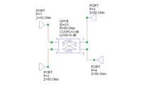
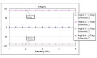
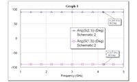
I was designing a hybrid coupler with Microwave office and i saw that the transmission port and the coupled port have at central frequency 90degree and 0degree (s21 phase). So for the coupled port it seems there is a lead: it is a bug or i can set some options to see the real delay? You can check this simply putting a ideal hybrid coupler with 4 port and displaying the phase of the s21
thanks
regards
 

Re: Hybrid coupler

Hello,

What exactly do you mean Real Delay?
Is the attached one do you referring in MWO???


Quadrature Hybrid (Closed Form): QHYB
This is an ideal behaviral model...

So you need to use the physical based model
Microstrip Branch-Line Coupler (Aggregate): MBLCOUP


---manju---
 

Re: Hybrid coupler

Thank you for the reply.
The hybrid coupler is coupled line (lets say a broadside coupler) and i saw this behaviour so i used the ideal hybrid to check the behaviour.
The real delay: a positive phase means a lead in the signal at the coupled port i suppose.
thanks
 

Status
Not open for further replies.

Part and Inventory Search

Welcome to EDABoard.com

Sponsor

Back
Top