Djsarkar
Member level 3

Hi
I have PIC18F45K80. I am using MPLABX 5.40 and XC8 2.30.
I have written code that supposed to sound the buzzer for 3 seconds and two seconds of silence and then repeat. When I Run code buzzer doesn't give any sound
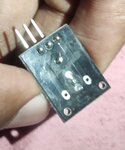
followed link https://www.thegeekpub.com/wiki/sensor-wiki-ky-012-active-piezo-buzzer-module/
code work fine If I use LED instated buzzer so I don't know what's the problem with buzzer
Code:
#define _XTAL_FREQ 8000000
#include <xc.h>
// PIC18F45K80 Configuration Bit Settings
// 'C' source line config statements
// CONFIG1L
#pragma config RETEN = OFF      // VREG Sleep Enable bit (Ultra low-power regulator is Disabled (Controlled by REGSLP bit))
#pragma config INTOSCSEL = HIGH // LF-INTOSC Low-power Enable bit (LF-INTOSC in High-power mode during Sleep)
#pragma config SOSCSEL = HIGH   // SOSC Power Selection and mode Configuration bits (High Power SOSC circuit selected)
#pragma config XINST = OFF       // Extended Instruction Set (Enabled)
// CONFIG1H
#pragma config FOSC = INTIO2    // Oscillator (Internal RC oscillator)
#pragma config PLLCFG = OFF     // PLL x4 Enable bit (Disabled)
#pragma config FCMEN = OFF      // Fail-Safe Clock Monitor (Disabled)
#pragma config IESO = OFF       // Internal External Oscillator Switch Over Mode (Disabled)
// CONFIG2L
#pragma config PWRTEN = OFF     // Power Up Timer (Disabled)
#pragma config BOREN = SBORDIS  // Brown Out Detect (Enabled in hardware, SBOREN disabled)
#pragma config BORV = 3         // Brown-out Reset Voltage bits (1.8V)
#pragma config BORPWR = ZPBORMV // BORMV Power level (ZPBORMV instead of BORMV is selected)
// CONFIG2H
#pragma config WDTEN = OFF      // Watchdog Timer (WDT disabled in hardware; SWDTEN bit disabled)
#pragma config WDTPS = 1048576  // Watchdog Postscaler (1:1048576)
// CONFIG3H
#pragma config CANMX = PORTB    // ECAN Mux bit (ECAN TX and RX pins are located on RB2 and RB3, respectively)
#pragma config MSSPMSK = MSK7   // MSSP address masking (7 Bit address masking mode)
#pragma config MCLRE = ON       // Master Clear Enable (MCLR Enabled, RE3 Disabled)
// CONFIG4L
#pragma config STVREN = ON      // Stack Overflow Reset (Enabled)
#pragma config BBSIZ = BB2K     // Boot Block Size (2K word Boot Block size)
// CONFIG5L
#pragma config CP0 = OFF        // Code Protect 00800-01FFF (Disabled)
#pragma config CP1 = OFF        // Code Protect 02000-03FFF (Disabled)
#pragma config CP2 = OFF        // Code Protect 04000-05FFF (Disabled)
#pragma config CP3 = OFF        // Code Protect 06000-07FFF (Disabled)
// CONFIG5H
#pragma config CPB = OFF        // Code Protect Boot (Disabled)
#pragma config CPD = OFF        // Data EE Read Protect (Disabled)
// CONFIG6L
#pragma config WRT0 = OFF       // Table Write Protect 00800-01FFF (Disabled)
#pragma config WRT1 = OFF       // Table Write Protect 02000-03FFF (Disabled)
#pragma config WRT2 = OFF       // Table Write Protect 04000-05FFF (Disabled)
#pragma config WRT3 = OFF       // Table Write Protect 06000-07FFF (Disabled)
// CONFIG6H
#pragma config WRTC = OFF       // Config. Write Protect (Disabled)
#pragma config WRTB = OFF       // Table Write Protect Boot (Disabled)
#pragma config WRTD = OFF       // Data EE Write Protect (Disabled)
// CONFIG7L
#pragma config EBTR0 = OFF      // Table Read Protect 00800-01FFF (Disabled)
#pragma config EBTR1 = OFF      // Table Read Protect 02000-03FFF (Disabled)
#pragma config EBTR2 = OFF      // Table Read Protect 04000-05FFF (Disabled)
#pragma config EBTR3 = OFF      // Table Read Protect 06000-07FFF (Disabled)
// CONFIG7H
#pragma config EBTRB = OFF      // Table Read Protect Boot (Disabled)


void Port_pins_Initialized (void)
{
    LATA = LATB = LATC = LATD = LATE =  0;
    TRISA = 0b0000000;// all are output, Unused
    TRISB = 0b0000000;// Buzzer connected to B0
    TRISC = 0b0000000;// all are output, Unused
    TRISD = 0b0000000;//
    TRISE = 0b0000000;// All are output, Unused

    ANCON0 = 0; // digital port
    ANCON1 = 0; // digital port
    CM1CON = 0; // Comparator off
    CM2CON = 0; // Comparator off
    ADCON0 = 0; // A/D conversion Disabled
}

void main(void)
{
  Port_pins_Initialized ();

    while (1)
    {
        LATBbits.LATB0 = 0;//Buzzer on
        __delay_ms(3000); // Wait for 3 seconds

        LATBbits.LATB0 = 1; //Buzzer off
        __delay_ms(2000);  // Wait for 2 seconds

    }
}


