Continue to Site

Welcome to EDAboard.com

Welcome to our site! EDAboard.com is an international Electronics Discussion Forum focused on EDA software, circuits, schematics, books, theory, papers, asic, pld, 8051, DSP, Network, RF, Analog Design, PCB, Service Manuals... and a whole lot more! To participate you need to register. Registration is free. Click here to register now.

Problem when connecting a full bridge inverter to output of a boost converter.

Status
Not open for further replies.

apollo_111

Newbie level 4
Newbie level 4
Joined
Mar 11, 2014
Messages
6
Helped
0
Reputation
0
Reaction score
0
Trophy points
1
Activity points
43
Hi friends.

I have trouble with my boost converter+inverter design. My boost converter is work proper itself but when I try to connect a full bridge inverter to output of the converter, converter output voltage dramatically drops down. Actually, I'm trying to have 220Vrms AC voltage from inverter output.

I'm waiting your help please.

My design without inverter (Boost converter output voltage is nearly 60V):

boost converter.PNG

After connecting the full bridge inverter:
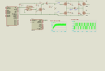
boost+inverter.png
 

Questions:

* Are you certain your boost converter can provide the amount of current you need? What happens when you reduce R2 to 50 ohms? 20 ohms?

* Are you certain that shoot-through is not occurring? Q2 and Q3 must never turn on at the same time. Nor Q4 and Q5.
 

Thanks for your quick reply BradtheRad,

Answers:

*When I reduce the R2 value, nothing has changed. Even when I make open circuit, the voltage doesn't change on boost converter and inverter output.

*Here are inverter triggering voltages:
gate voltages.PNG
 

Can you test whether Q2 and Q4 are turning on fully?

They appear to be N-mos.
Their gates are referenced to their source.
Their source needs to see a definite path to ground, so that voltage applied to the gate is high enough to turn on the device.

If this is not the case, Q2 and Q4 will not turn on fully. Then you will need to elevate the voltage applied to their gates.
 

Can you test whether Q2 and Q4 are turning on fully?
You don't need to test it, they can't by design. Level shifting high side gate drivers are missing. Even low side transistor don't turn-fully on with 5V Vgs, by the way.

To understand boost converter operation we need to know the control waveform (frequency and duty cycle).
 

You don't need to test it, they can't by design. Level shifting high side gate drivers are missing. Even low side transistor don't turn-fully on with 5V Vgs, by the way.

To understand boost converter operation we need to know the control waveform (frequency and duty cycle).

Here is the boost converter control signal : (Duty Cycle =%90 1us off 9 us on, Freq= 100kHz)

boost_control.PNG

So, what kind of gate driver sould I use inorder to turn fully on the mosfets?

- - - Updated - - -

Thanks for gate driver advice.I connected an IR2101 to circuit. I turned inverter full bridge to half bridge. I changed boost converter frequency to 1kHz (900us on, 100us off).However, my simulation stops near 50us. Do you have any idea how can I fix it? And I also want to have 310Vpeak AC (220Vrms) from inverter output.
View attachment deney3_half bridge.png
 

I reviewed the simulation result in post #1 and found that the voltage limitation below 60 V can be explained with IRZ44 avalanche breakdown (Vds,max = 55V). The same can be expected in your latest simulation.

This brings up the question how you are selecting components and other circuit parameters like boost converter switching frequency. Only few things seems to be in the right ballpark.
 

Maybe it's better to use IGBTs and their gate drivers instead of MOSFETs. I'm planning to design a 5 kW inverter which has tunable input voltage by boost converter. As you say, I need some calculations for boost converter switching freq. and inductance value...I have to decide which IGBT and driver I'm going to use first :S

Do you know any book for this calculations and design tips ?
 
Last edited:

To run at 5kW of power you might as well consider going back to using a full H-bridge. That is the classic efficient method to obtain positive-and-negative polarity AC, at the amplitude you want.

Even if you end up keeping the boost converter, consider joining multiple interleaved boost converters. This has benefits:

(a) smoothing current ripple taken from the DC power supply,

(b) sharing the heavy current load among several components,

(c) lessens current spikes into and out of the smoothing capacitors.
 

Above a certain boost factor, e.g. 3 or 4, a single inductor boost converter becomes inefficient compared to a transformwr converter. The reason it that switching losses are in a first order related to switched power which is input current multiply output voltage for a boost converter.
 

I found an IPM (intelligent power module) for my application, but I need some information about how to controll it.

https://www.farnell.com/datasheets/93226.pdf

Anyone can help me ?

- - - Updated - - -

Thanks for your advices FvM. I found an IPM (intelligent power module) for inverter. I think I can make a full bridge using 2 of this equipment. But I couldn't find any application note about it. I need some information about how to connect it to circuit and control.

https://www.farnell.com/datasheets/93226.pdf
 

There must be additional data sheets which explain how to use that IC, or that series of IC's (RH-series).

I do not know all about such IC's, but it's possible you would only need one.
The internal schematic shows 6 driver IGBT's. Your H-bridge will use four of them. The load will go across pins U and V.

I could be wrong.
 

Status
Not open for further replies.

Part and Inventory Search

Welcome to EDABoard.com

Sponsor

Back
Top