allennlowaton
Full Member level 5

Good day guys!!!
Your ideas are highly needed regarding this matter..
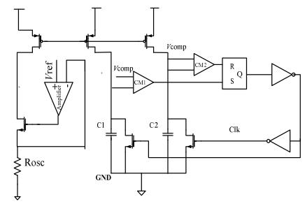
the circuit shown is an oscillator with frequency spread that will be used for a PWM controller.
I had a simulation on the circuit shown. At first, I used an ideal clock for the two NMOS which paralleled the capacitors. I obtained a reasonable output.

NOTE: THE OTHER VCOMP IS NOT CONNECTED WITH THE OTHER INPUT ON CM2
The problem comes in when I completed the loop. Node on capacitor1 (C1) don't charge yet node on C2 don't discharge too.
Please share your idea on what to do.
Thank you.
Your ideas are highly needed regarding this matter..
the circuit shown is an oscillator with frequency spread that will be used for a PWM controller.
I had a simulation on the circuit shown. At first, I used an ideal clock for the two NMOS which paralleled the capacitors. I obtained a reasonable output.

NOTE: THE OTHER VCOMP IS NOT CONNECTED WITH THE OTHER INPUT ON CM2
The problem comes in when I completed the loop. Node on capacitor1 (C1) don't charge yet node on C2 don't discharge too.
Please share your idea on what to do.
Thank you.

