Continue to Site

Welcome to EDAboard.com

Welcome to our site! EDAboard.com is an international Electronics Discussion Forum focused on EDA software, circuits, schematics, books, theory, papers, asic, pld, 8051, DSP, Network, RF, Analog Design, PCB, Service Manuals... and a whole lot more! To participate you need to register. Registration is free. Click here to register now.

Problem during simulating active inductor with ADS simulator

Status
Not open for further replies.

noor84

Member level 5
Member level 5
Joined
Dec 27, 2017
Messages
90
Helped
0
Reputation
0
Reaction score
0
Trophy points
6
Visit site
Activity points
688
Dear Friends,
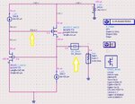
I am designing Simple active inductor as in the pic1 (in the attachments)
My circuit problem is:
when I biasing DC for 50 uA and simulate it, all are ok (the current in Drain 1 and 2 is alright 50uA and the voltages).
But when I connect the term(Term1) with (50 Ohm) and simulate to measure (L and Q) the current drop to 7 mA and the voltages changes.
My question:
is it Ok for changes of voltages and currents?
The term1 will affect the value of inductance and quality factor when the current drop?
Please, see the pics in the attachments files.
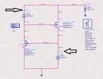
1.jpg
2.jpg
 

is it Ok for changes of voltages and currents?/QUOTE]

You are changing the loading the circuits. Its quiet expected for this to happen...

Dear vivekroy ,
Thank you for the reply,
The current rise to (1.7 mA) instead of (50uA).
How can I calculate the power((Id1+Id2)*Vdd)?
Will the power measure at DC (Pic1) or at S-parameters measure(Pic2)?
 

is it Ok for changes of voltages and currents?
It's not Ok if you want to keep the active inductor function. In case of doubt use AC coupling for the connected external circuit.
 

It's not Ok if you want to keep the active inductor function. In case of doubt use AC coupling for the connected external circuit.

Thanks for reply.
I have to design and simulate active inductor and the currnt should be 50uA.
But when I connect The term1 to get S-parameters to get the (L) and (Q) From Z11.
The currents(Id1)at (Transistor1) and voltages changes.
Please,how can I simulate without change?
How can I connect(AC coupling for the connected external circuit).?
Did you mean I should remove term1?
If I did that.
How can I measure L and Q Without Term1?
 

AC coupling is usually performed by a sufficient large series capacitor.

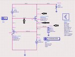
I connect (DC_Block1) founded in the ADS.
Is this connection is right? (When I simulated I see all currents and voltages are right as I calculated theoretically)
Please see the pic.

3.jpg
 

Yes, DC block is perfect.

Many thanks for your help.

Please, I have to measure (Cgs1 and Cgs2) using the simulator (ADS) but as shown in the pic below, there is no value for Cgs!!
One thing also, how can I measure the operating frequency(F0) of the inductor? and Q?
I mean, when I calculated the frequency theoretically(F0=sqrt((gm1*gm2)/(Cgs1*Cgs2))) I get (F0=1.67GHz), how can I see it on data simulation?

4.jpg
 

Why BULK Pins are not connected ?? They should be connected to SOURCE or lower potential (GND)
 

Why BULK Pins are not connected ?? They should be connected to SOURCE or lower potential (GND)

Hi BigBoss,
The second step of the design I will connect the bulk,
But now I am I have to learn how to measure (Cgs1 and Cgs2) using the simulator (ADS) but as shown in the pic below, there is no value for Cgs!!
One thing also, how can I measure the operating frequency(F0) of the inductor? and Q?
I mean, when I calculated the frequency theoretically(F0=sqrt((gm1*gm2)/(Cgs1*Cgs2))) I get (F0=1.67GHz), how can I see it on data simulation?

4.jpg
 

Looks like the two MOSFETs don't use the right model.

Which inductance do you see in AC simulation?

In the process parameters model, The values of (cgs0 and cgd0 ....) are there as shown in the previous pics.
I use S-parameters to measure the value of the circuit inductance that is in the side of (Term1).
 

I don't recognize if the bsim3 model is instantiated for the two transistors, apparently it's not.
 

I don't recognize if the bsim3 model is instantiated for the two transistors, apparently it's not.

I attached pic please see it.
The two transistors have the same name model(bsim3 ).
I have the problem with F0, Q, L, may you tell me how can I get the resonant frequency from ADS and Q, L?
Please guide me to " how can I get the resonant frequency from ADS and Q, L"

5.jpg
 

Status
Not open for further replies.

Part and Inventory Search

Welcome to EDABoard.com

Sponsor

Back
Top