Probing and scoping MegOhm circuits?
- Thread starter cupoftea
- Start date


- Joined
- Jan 22, 2008
- Messages
- 53,653
- Helped
- 14,809
- Reputation
- 29,907
- Reaction score
- 14,418
- Trophy points
- 1,393
- Location
- Bochum, Germany
- Activity points
- 303,380
Many 10 Mohm probes available on the market:Thanks, i am not aware of too many 10Meg probes...the common ones i know of all have 1MEG shunt and 9 MEG series if 10:1, or 1MEG shunt and 99MEG series if 100:1?
In earlier years, most 10:1 probes had 10 Mohm input R, increased bandwidth of modern passive probes often resulted in 1 Mohm.
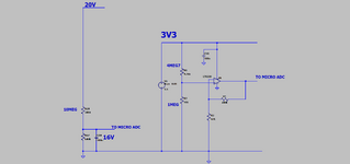
Base node has 200 nA bias, 1 Mohm probe turns transistor off.
kd502
Newbie level 5

Voltage follower with opamp can be adequate active probe for this circuit. If you want, you can build the probe with high speed opamp, and low bias current (CMOS) for future use, but this circuit doesn’t need it.
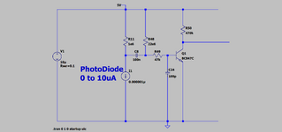
I have been using 100M-1Gohm resistors in transimpedance amplifiers, 22MOhm doesn't look like an "elephant in the room"
I have been using 100M-1Gohm resistors in transimpedance amplifiers, 22MOhm doesn't look like an "elephant in the room"


cupoftea
Advanced Member level 6
Thanks yes, though i believe there are noise issues (as well as what FvM kindly points out) with around 22MEG and above.I have been using 100M-1Gohm resistors in transimpedance amplifiers, 22MOhm doesn't look like an "elephant in the room"
...When you consider that in SMPS feedback loops, its pretty well taken as a golden rule that you need to keep upwards of 100uA in your output divider resistors otherwise your feedback signal is in danger of being drowned in noise. Obviously this applies especially to SMPS with transconductance error amplifiers where its the actual ratio of the output divider resistors which counts, rather than the value. This applies even to low power , low voltage DCDCs which when well layed out, dont spew loads of noise over these resistors.
I also remember some Guys from Japan coming over to buy a product from us....and them going nuts because they said they had seen a thumb print on a 10 MEG resistor. As you know, such impurity on a 10MEG can dramatically alter its effective value....(the resistance value "seen" between its pads.)
I would hate to think of a 22MEG with some dampness over it or dust coating......even if it had been coated over with conformal coating.
The cheapness of many standard electronics products doesnt allow for the extra manufacturing details which are needed for sucessful use of multi MEGOhm circuits.
Last edited:
D.A.(Tony)Stewart
Advanced Member level 7
- Joined
- Sep 26, 2007
- Messages
- 10,231
- Helped
- 1,866
- Reputation
- 3,735
- Reaction score
- 2,497
- Trophy points
- 1,413
- Location
- Richmond Hill, ON, Canada
- Activity points
- 64,569
Whenever I see a discrepancy, I always wonder, what are the differences in assumptions.
I never hesitated to use 33 Meg resistors for low f CMOS logic gates in my late '70's Aerospace days. For environmental protection, I added Silicone spray or more harsh environments like atmosphere reentry... GE RTV which even prevents exposed wires from getting melted or for RF ... tin-plated shields. They do make bigger resistors and Omega meters
"If probing the attached with say a scope probe, would you recommend a 100:1 probe?"
- Only if desperate. I'd only probe the lower impedance points to imply the performance, which is what I was thinking, by measuring the Vbe instead. But, I was lucky to have Tek FET probes where ever I worked, which requires critical care of any voltages or ESD E-fields> 25V.
Frank you are correct! Your simulation proves 2uA is insufficient with a 1:1 scope probe on the 22 Meg resistor.
So I examined our differences in assumptions to understand the disparity in simulations,
1. Was it differences saturation current, Is for the transistor? I used 100 fA, The BC547A in LTspice is 4.679 E-14, possibly
2. Was it hFE which drops rapidly with Ic < 5 uA and has a wide tolerance? Possibly, I used hFE =50 ( spec is 90 nom. at 10uA)
3. Was it the input pulse freq.? LTspice used 100 Hz, I used > 5kHz , Yes it makes a difference to the transistor .
4. Was it the probe test point? Yes, I assumed Vbe as the critical test point, as the 47k 100 pF + probe attenuates the ripple and Rbe is a lower impedance at 2.6 uA
Last edited:
kd502
Newbie level 5
Don't know application of this circuit, but it can detect pulses <300nA all circuits with this sensitivity are sensitive to external noise.Thanks yes, though i believe there are noise issues (as well as what FvM kindly points out) with around 22MEG and above.
Someone can make 300nA circuit with <1Mohm resistors. Sensitivity to leakage and mains hum will be similar.
It is good practice to keep it clean. Did anyone measured this dramatic change? I can touch 100Mohm (1206) and there is no dramatic change.I also remember some Guys from Japan coming over to buy a product from us....and them going nuts because they said they had seen a thumb print on a 10 MEG resistor. As you know, such impurity on a 10MEG can dramatically alter its effective value....(the resistance value "seen" between its pads.)
It depends on voltage. Guard rings on PCB can nullify voltage and surface leakage.I would hate to think of a 22MEG with some dampness over it or dust coating......even if it had been coated over with conformal coating.
Similar threads
-
-
HELP!! The derivation of the quality factor(Q) for series and parallel circuits.
- Started by TingtingEva
- Replies: 1
-
How to reduce the crossover distortion of push-pull circuits?
- Started by vbsemi
- Replies: 2
-
Measurement of power rail impedance and inductance and plane capacitance
- Started by FreshmanNewbie
- Replies: 0
-
How to calculate Propagation Delay in Domino CMOS circuits.
- Started by Manjunath557
- Replies: 0