Vermes
Advanced Member level 4

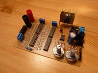
Power supply features:
- continues voltage adjustment from 0 to 20V
- continues current limit adjustment from 0 to 2A
- diode signalization of current limit switched on
- built-in analog voltage and current gauge
- different types of input and output sockets
- overheat protection
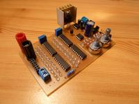
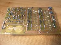
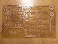
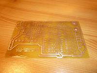
Where the transformer is:
This power supply uses an external Dell PA-9 supply with DC 5.5/2.1mm round socket. But it also can be powered from Nokia loader with DC 3.5/1.1mm socket (DCPS1813). All can be connected at once, getting maximum 35VDC.
LM317 stabilizer:
This is a basic diagram of the LM317. It adjusts from 1.25 V to the voltage-dependent resistance of the potentiometer, a current limiter is built into the system and set rigidly.
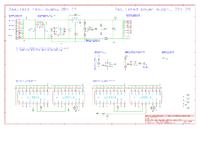
On the internet, some information about arousing the stabilizer can be found. Some information say that big capacitors should be mounted to prevent the stabilizer from arousing. It's justified, using some capacitors on the input for filtering the voltage after the rectifier bridge, but there is no justification for big capacitors on the output. The documentation says that the capacitors should be maximum 10uF (with selection that it should be a tantalum capacitor, not electrolyte).
In this supply a 1000uF capacitor was mounted. It aroused every time! The LM317 was really hot, and when the current limiter switched on, the stabilizer squealed! To solve the problem, the second output capacitor was unplugged.
The same with DO1 and DO2 diodes. They are used to unload the capacitors, when the circuit is closed. Elements marked with an asterisk (DO1, DO2, C7 and C8) are on the PCB, but it can be said they shouldn't be plugged in.
The LM317 is designed to work with the current 1.5A (as in documentation). From this device, current of value 2A can be reached – which should damage the chip. It's overloaded but it doesn't damage, because it has it's own collateral. If someone wants to get more:
- LM350 to 3A
- LM338 to 5A
- LM396 to 10A
How does the adjustment from 0V work when LM317 gives on output 1,25V? The 1,25 is on R1 resistor. This resistor is usually connected to ground – it should be connected to negative voltage! Then the voltage across the resistor and the negative tension will abolish.
Parallel to POT1 is connected a current limiter transistor. This transistor is an imitation of a potentiometer – is reduces the tension of the supply not to allow to exceed the allowed value. What is the current? The flow causes tension to reduce on R6. It's not a big reduce because on 2A flowing through 0.1R it causes 0.2V reduce. This tension is compared with the reference voltage (set by POT2). When the tension on the measuring resistor is bigger than threshold voltage, then the comparator switches on and opens the transistor, and that reduces the powering voltage on output of LM317. Switch on the limiter is signalized by a yellow led near the current adjusting potentiometer.
The regulation circuit needs symmetrical +5V and -5V. The positive voltage is from 7805 (in TO92 housing), therefore, the minimal voltage applied to the input is 7V (otherwise, the current limit will not work well). The negative voltage is from ICL7660.
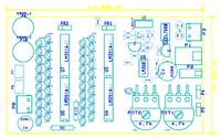
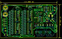
Voltage and current measure:
The measure is indicative, it's based on an analog-digital converter LM3914. How does it work: Leon Instruments: Amperomierz LM3914
The green diodes are the voltmeter. One diode equals 1V (for example 5 diodes means that on the output is 5V).
The red diodes are the intensity meter. One diode equals 0.1A.
There is 20 diodes of each color, therefore the measure is to 20V and 2A.
It's good to buy energy saving diodes, if not, 40 lighting diodes will take 0.8A (20mA each)! Good power saving diodes take about 1mA. The lightness of the diodes is adjusted by the current from REF OUT output of LM3914 – the current of each lightened diode is 10 times bigger than the current output from REF OUT. The R11, R12, R13 and R14 resistors should be chosen, so that the diodes' light is seen and the current is optimal. It should be considered, that R12 and R14 are parallel connected by a 47kOhm potentiometer.
The calibration of the measures is very simple. Firstly, the voltmeter is calibrated. A normal voltmeter should be connected on output and with potentiometer POT1, should be rotated to set 19V. Next using PR1 should be rotated to lighten 19 green diodes.
The calibrate the current meter will require a load – it could be a bulb from a car. It must be connected series with the ammeter and connected to the power supply. Using POT1, the current should be adjusted to 1,9A, than using PR2 19 red diodesok should be lightened.
Usage example:
The bulb is powered by 20V (20 green diodes) and consumes 1A (10 red diodes)
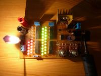
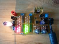
The voltage was reduced to 9V – the bulb takes 0.6A
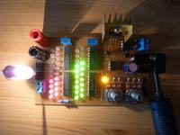
The yellow LED signalizes the current limiter operation. The limiter is set to 0.8A, 16V set itself.
Link to original thread – Zasilacz NIE z electronics lab
