Jaggions
Newbie level 3

Hi. After reading some guides on the net, I decided to make my own power supply starting from an ATX PSU. I wrote down a sort of project and I'd like to know if in your opinion it's OK so that I start making it.
Materials:
Description:
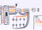
The male ATX connector from the PSU is connected to a female ATX connector. We need to solder to it one +5V red wire, two +12V yellow wires, two +3.3V orange wires, two -12V blue wires and five COM black wires. Furthermore, we have to short the PS.ON pin with a COM one.
One of the +3.3V wires and one of the COM wires go directly to the green LED, indicating that the power supply is powered on. All the other wires go throughout the voltmeter and the ammeter.
Then one +12V wire and one -12V wire are connected to a potentiometer (so that it can give voltage from 0V to 24V) which outputs to a pair of binding posts.
The other wires end with eight binding posts (+3.3V, COM, +5V, COM, +12V, COM, -12V, COM) providing a fixed voltage.
And that's it; all this starting from the female ATX goes into the project box.
To make it easier to understand, I made a drawing of what's inside the project box:

What do you think? Is it ok? Would you change something?
Edit: I just noticed that the voltmeter shouldn't be placed there as it would be useless; it has to be placed between the potentiometer and the binding posts so that it measures the voltage outputted buy the potentiometer.
Materials:
- ATX PSU
- Solder
- ATX female connector
- Drill
- Project box
- 10x binding posts
- Potentiometer
- Green LED
- Voltmeter
- Ammeter
Description:
The male ATX connector from the PSU is connected to a female ATX connector. We need to solder to it one +5V red wire, two +12V yellow wires, two +3.3V orange wires, two -12V blue wires and five COM black wires. Furthermore, we have to short the PS.ON pin with a COM one.
One of the +3.3V wires and one of the COM wires go directly to the green LED, indicating that the power supply is powered on. All the other wires go throughout the voltmeter and the ammeter.
Then one +12V wire and one -12V wire are connected to a potentiometer (so that it can give voltage from 0V to 24V) which outputs to a pair of binding posts.
The other wires end with eight binding posts (+3.3V, COM, +5V, COM, +12V, COM, -12V, COM) providing a fixed voltage.
And that's it; all this starting from the female ATX goes into the project box.
To make it easier to understand, I made a drawing of what's inside the project box:

What do you think? Is it ok? Would you change something?
Edit: I just noticed that the voltmeter shouldn't be placed there as it would be useless; it has to be placed between the potentiometer and the binding posts so that it measures the voltage outputted buy the potentiometer.


