Continue to Site

Welcome to EDAboard.com

Welcome to our site! EDAboard.com is an international Electronics Discussion Forum focused on EDA software, circuits, schematics, books, theory, papers, asic, pld, 8051, DSP, Network, RF, Analog Design, PCB, Service Manuals... and a whole lot more! To participate you need to register. Registration is free. Click here to register now.

Power Supply for M95 GSM module to be compatible with ATEX limitations.

Status
Not open for further replies.

hm_fa_da

Full Member level 5
Full Member level 5
Joined
Sep 16, 2003
Messages
287
Helped
10
Reputation
20
Reaction score
4
Trophy points
1,298
Activity points
3,217
Hi,

I am going to use Quectel M95 GSM Module in an IS circuit for Zone 1.
According to Type examination certificate of M95:
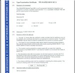
M95ATEX.jpg

As you see in the file, it's mentioned: Ui(max)=<4.2V, Ii(max)=2.1A, Pi(max) =<2W.

As i know, i have to make a power supply which has limited parameters compatible with M95 Module values, means:
Uo(max) <4.2V, Isc(max)<2.1A, Po(max) <2W to keep the M95 Module in intrinsically safe state.

But current limiting is not possible by simply using a resistor, because in that case i need to use a 2ohm resistor which stops module working fine in normal conditions (because of high voltage drops result of pulse current sinking of GSM module - up to 1.6A )

So the only solution is using Active current and Active power limiters !
Is this right ?
and because of using device in Zone 1, i have to use 2 series of each Current and power limiters ... which seems little strange !

Note that I just need the maximum antenna radiation of the module to stay lower than 3.5W, Because i want to use whole GSM circuit and module in an encapsulation according to ATEX, but the antenna will be out of encapsulation, so antenna radiation should be still limited down to <3.5W to be compatible for gas group IIB.

The complete ATEX Type examination certificate PDF of M95 is Attached.
 

Attachments

  • Quectel_M95(R2.0)_ATEX_Certificate.pdf
    753.8 KB · Views: 151

Hi,

This certificate is no datasheet.
Go to the manufacturer's internet site and look for the datasheet and design notes.

Klaus
 

Hi,

This certificate is no datasheet.
Go to the manufacturer's internet site and look for the datasheet and design notes.

Klaus

Thanks,
There is nothing about IS considerations in the Module Datasheet, neither design note.

In fact my question is that if i do not limit the current to the module to a value lower than 2.1A, then according to that certificate, the module would not be IS (intrinsically safe) ?

If i have to limit it to 2.1A, as you know there is 1.6A pulses when the GSM module is working in normal mode. i.e using a 2ohm resistor in series with power line will make 2 x 1.6 = 3.2V drop which turns the module off ...
 

Hi,

I don´t know the IS regulations.

Resistor as current limiting device in a power supply is not usefull at all, thus the power supplies are equipped with true current limiter circuits.
They guaratee a rather constant voltage within the specified current, but at overcurrent condition the voltage drops rapidly.

* look for power supplies with (adjustable) current limit feature.
* or check if a polyfuse is suitable

Btw: DC power = V x I. Now your specifications are 4.2V and 2.1A(p) this gives 8.82W(p). Thus the given 2W specification can be average power only. Sadly averaged over an unknown period of time.

Klaus

Added:
I´m not surprised that the datasheet contains no IS informations. But it contains all necessary specifications about the drawn current and the necessary voltage stability.
In the application not there is a "Reference Design for Power Supply". Not sure what you need to add that it becomes IS compliant.
 
I was involved in a power supply design for a GSM module.
It was not for ATEX, so maybe you have no use for this information.
When we calculated the capacitance needed to keep the supply voltage within limits during the high current pulses, we saw that it was much more than we wanted (considering board space and cost).
We solved the problem by putting less capacitors on a higher voltage node, and using a very fast linear regulator for the GSM module power supply.
The capacitors could be discharged a few Volts during a pulse, but the fast linear regulator kept the GSM module supply voltage within limits.
 
I did a Zone 0, IS cell modem design. Main power is a 6V lead-acid battery. 60079-11 does not allow active current-limiters. I used an LDO for 3.7V 2A power to the modem module. I thought a buck-converter would be too noisy for the range needed and fringe reception. If you can't current-limit then an IS fuse is acceptable.
 

I did a Zone 0, IS cell modem design. Main power is a 6V lead-acid battery. 60079-11 does not allow active current-limiters. I used an LDO for 3.7V 2A power to the modem module. I thought a buck-converter would be too noisy for the range needed and fringe reception. If you can't current-limit then an IS fuse is acceptable.

Thanks all for replies,
Did you get a lab certification for your design ?
As I know active current limiters are allowed but it should be used like double current limiter circuits for ib at least.
the way you regulated the voltage by an LDO is not voltage guaranteed, maybe the circuit be IS, but the 3.7V is not guaranteed (if the regulator fails to short circuit).
your circuit connected to LDO output may be still safe if regulator fails (depends on the circuit) but in my case, as i know, it should be guaranteed to be less than 4.2V so the GSM module stay IS ...
using fuse is not a solution here, because we should multiply the fuse rating by 1.7, so using a 2A fuse is considered to be 5.1A !
 

I don't see that any of the V, I or P limits can be achieved other than with active electronic circuits. There are some issues like avoiding additional L and C elements in the IS circuit that may thwart the safety limits. It's quite nice that Quectel has the ATEX certificate, but making an IS power supply for it is still a hard job.

According to the comment that this isn't an equipment certificate, I wonder what are the requirements for an intrinsic safe GSM antenna and it's mounting restrictions?
 

Status
Not open for further replies.

Part and Inventory Search

Welcome to EDABoard.com

Sponsor

Back
Top