Continue to Site

Welcome to EDAboard.com

Welcome to our site! EDAboard.com is an international Electronics Discussion Forum focused on EDA software, circuits, schematics, books, theory, papers, asic, pld, 8051, DSP, Network, RF, Analog Design, PCB, Service Manuals... and a whole lot more! To participate you need to register. Registration is free. Click here to register now.

Power supply for ADC chip Analogue Grounding Question

userx2

Full Member level 3
Full Member level 3
Joined
Sep 19, 2008
Messages
177
Helped
2
Reputation
4
Reaction score
3
Trophy points
1,298
Activity points
3,092
Hello,

I am just designing the power circuit for a 24bit ADC chip interfacing to a microcontroller on the same PCB.
The manufacturer recommends separate regulators for the digital and analogue side. Fair enough.
But I am confused about the grounding configuration.
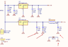
I thought the output caps of the analogue (3.3A) regulator should go to AGND but in this circuit, they have connected then to the Digital GND.

The ADC chip AGND pins and local decoupling caps are the only parts connected to the AGND.

Is that correct and what would be the reasoning behind that configuration?
Please see picture

Best regards
X
 

Attachments

  • Analog Voltage Ground1.png
    Analog Voltage Ground1.png
    38 KB · Views: 232
  • Analog ADC Grouind 2.png
    Analog ADC Grouind 2.png
    55.4 KB · Views: 153
Hi,

you refer to an ADC
and to a datasheet.

But you hide the manufacturer/type of ADC
and you don´t give a link to the datasheet.

This makes helping difficult. We can not find out what the datasheet really says and how they meant the whole power supply system to work.
We can not validate the given informations.

And it needs time to write this post.

From your post we just have two values we can calculate with: "24 bit" and "3.3A" ... while I doubt at least one of both.

Klaus
 
I did not want to cloud the question with a lot of unnecessary information as my question is regarding grounding.
Perhaps I should have chosen a different heading but I could not think of a better one at the time and now it cannot be edited.

The question I have is purely regarding analog / digital grounding and decoupling thereof in general. the fact that this is an ADC chip has not actual relevance as it could even be an audio amplifier with digital processor or whatever.

I personally have not seen regulator decouplers ground back to digital ground but I am willing to learn if there is an advantage.

If you think a datasheet will be useful, here it is:
https://ww1.microchip.com/downloads...-Six-Channel-Analog-Front-End-DS20005227C.pdf

Best regards
X
 
I'd like to refer to my statement in a previous post
In mixed signal design with multiple analog and digital functions, there's no reasonable way to use separate analog and digital grounds. A continuous common ground plane is the usual solution. Separate power supplies may be helpful, but more important to bypass the power supplies near each mixed signal device.
--- Updated ---

Another related previous discussion
 
Last edited:
Hi,

unnecessary?
But it was you who referred to the datasheet. So if you think it is unnecessary .. why did you read it at all?
I can answer it: Because it is by far not unnecessary, it is essential instead!
It tells you how to use the chip correctly.

the fact that this is an ADC chip has not actual relevance as it could even be an audio amplifier with digital processor or whatever.
For sure you may read an "audio amplifier´s datasheet" if you think it makes sense.
This means you know better than the ADC chip manufacturer. Not impossible.

****
--> Analog / digital grounding depends how the ADC manufacturer designed the chip internally. And how they meant the chip/PCB to work and how they test the chip and how they gurantee the specified quality.

In the datasheet they explain in detail what to do: In several sections:
* 3.1
* 3.5
* 3.6
* 7.2
With text, with schematics, with sketches for PCB recommendation.
And they even provide an evaluation board including full schematics and full PCB layout.
(I´d say they did a good job, you are free to call it useless)

I thought the output caps of the analogue (3.3A) regulator should go to AGND but in this circuit, they have connected then to the Digital GND.
In my eyes their approach fully makes sense. The regulator is located outside the analog section .. still I recommend the analog supply regulators to be located near the ADC. The star point of both GNDs should be located close to the ADC .. inbetween regulators and ADC.
So regelulators refer to DGND .. then there are the series resistors for decoupling between AGND and DGND ... and then there are the ADC_capacitors referring to AGND.

In best case the series resistors are located exctly above the split between AGND and DGND.

You are free to go your own way. I don´t want to push you into something you don´t want to do.
I can only say that I used the "little brother" of your adc (MCP3911) and got better performance than specified as "typical". I tested them thoroughly.
So can assure the specified performance is valid. (rather impressive for the low cost. Still there are better (and more expensive) ADCs)

If you encounter any different ... don´t complain.

Klaus
 
Ohh I see,

You mean that the analog section only starts AFTER the 10Ohm series resistor. In that case, it would make sense to decouple only from there onwards to AGND.

regarding this ADC MCP3913...
I do not like that chip particularly, given the Errata. However, it seems the only reasonably priced 24bit chip available that has enough differential channels (6) for the project I am working on. This design requires 5 channels and the signals from the force sensors in question are very small. in the upper nV range.
I am actually really worried about noise.

Best regards
X
 
You mean that the analog section only starts AFTER the 10Ohm series resistor.
placement wise..

in the upper nV range.
I am actually really worried about noise.
you will need amplifiers.
And if the sensor signals are in in the nV range, then sensor supply, sensor wiring, shielding and filtering needs to be done very carefully.

Klaus
 
placement wise..


you will need amplifiers.
And if the sensor signals are in in the nV range, then sensor supply, sensor wiring, shielding and filtering needs to be done very carefully.

Klaus
Yes, ideally I need amplifiers with a gain of 1000 or even 1500.
However, they have given the bridge offset/imbalance manufacturing tolerance for this sensor +/-200mV (@3V power) which makes DC signal amplification impossible without more complex external circuitry to remove this initial bias.
When I questioned this, all I got was referral to an application circuit that shows the sensors directly connected to a CPU with 24bit Sigma Delta ADC.

Best regards
X
 
Hi,

hopefully you recognized the ADC´s ENOB to be somewhere worse than 16 bits.

If you want some signal quality ... then you will need an amplifier, maybe not that high gain, and equipped with a pot for offset adjustment.
For sure digital pots would make the offset adjustment as easy as pressing a button.
What´s the expected data rate per channel?

Also mind the offset DRIFT of typ. 500nV/°C.

Klaus
 
Last edited:
Hi,

hopefully you recognized the ADC´s ENOB to be somewhere worse than 16 bits.

If you want some signal quality ... then you will need an amplifier, maybe not that high gain, and equipped with a pot for offset adjustment.
For sure digital pots would make the offset adjustment as easy as pressing a button.
What´s the expected data rate per channel?

Also mind the offset DRIFT of typ. 500nV/°C.

Klaus

Hi Klaus, group,

My biggest problem in this design is space. there are 5 sensors cramped into a space of less than 50mm diameter and PCB can only have components on one side. Using this ADC in QFN + external oscillator + peripheral components (0402) already takes most of the space and I also still need a CPU chip.

Do you think such a low signal level is suitable for multiplexing through a Analog MUX / Switch?
In that case, one amplifier circuit may work for all 5 channels.

The data rate: I need about 20 - 25 samples per second. So not fast at all.
--- Updated ---

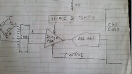
I have discovered that the proprietary chips (cannot mention them :-( ) have built in offset compensation +/-380mV built using a 12bit DAC as shown here, and also a programmable amplifier.

The Microchip MCP3913 has a PGA as well but no offset compensation.
I have not (yet) found any ADC chips with such offset compensation.

I am wondering if this compensation is a simple as just injecting the output of the a DAC through a resistor onto the + signal of the sensor output
 

Attachments

  • thumbnail.jpg
    thumbnail.jpg
    167.6 KB · Views: 82
Last edited:
I thought the output caps of the analogue (3.3A) regulator should go to AGND but in this circuit, they have connected then to the Digital GND.

The ADC chip AGND pins and local decoupling caps are the only parts connected to the AGND.

Is that correct and what would be the reasoning behind that configuration?
Please see picture

Best regards
X
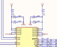
The reason is in order to have an accurate Ground for the ADC, there must be one and only one point of reference for ground from which all return currents flow independently of this measurement. It is commonly called a Star-ground as this point is the centre of the star. It may be supplied by a low impedance ground plane, but there is still only one point. This because Ground by definition means 0V and can only exist at one point unless the shared points have no current flowing between them.

This is shown on page 56 of the datasheet when I searched for "ground".

1715214772959.png
 
The reason is in order to have an accurate Ground for the ADC, there must be one and only one point of reference for ground from which all return currents flow independently of this measurement. It is commonly called a Star-ground as this point is the centre of the star. It may be supplied by a low impedance ground plane, but there is still only one point. This because Ground by definition means 0V and can only exist at one point unless the shared points have no current flowing between them.

This is shown on page 56 of the datasheet when I searched for "ground".

View attachment 190645

In this diagram, all decoupling caps after the VA supply got to AGND, which is what I thought it should be but in the schematic I asked about, also in (this datasheet somewhere), the decoupl ing capacitors after the VA to DGND instead. That is why I asked.
 
In this diagram, all decoupling caps after the VA supply got to AGND, which is what I thought it should be but in the schematic I asked about, also in (this datasheet somewhere), the decoupl ing capacitors after the VA to DGND instead. That is why I asked.
Sorry TL;DR your diagrams
Please show your assumptions. I do see a contradiction.
What does you logic suggest for Agnd current effects using the Avdd cap on Dgnd ? ( low AC current and only low DC current ??)
Let's tell Microchip how to correct their logic diagram.
They suggest it is sometimes easier to bulk up on e-caps and tie Avdd and Dvdd together.

Another possibility, sometimes easier to implement in
terms of PCB layout, is to consider the MCP3913 as an
analog component, and therefore, connect both AV DD
and DV DD together, and A GND and DGND together, with
a star connection. In this scheme, the decoupling
capacitors may be larger due to the ripple on the digital
power supply (caused by the digital filters and the SPI
interface of the MCP3913) now causing glitches on the
analog power supply.
FIGURE 7-2: All Analog and Digital
Return Paths Need to Stay Separate with Proper
Bypass Capacitors.
FIGURE 7-3: Power Supply with Separate Lines for Analog and Digital Sections. Note the “Net Tie”
Object NT2 that Represents the Start Ground Connection.


My conclusion

I think they are suggesting several ways to solve this problem and the assumption must be that the current must not change between Vd and Va or Dgnd and Agnd for the constant current Op Amps and S&H circuit between Start & Stop for the ADC conversion to be accurate and free of monotonic errors. Yet no where does it prove this that Vdd noise is isolated from Va to Agnd.

Yet that assumes GNDB or Dgnd or 3.3Vd does not shift Agnd and cause analog Vref noise errors. This requires a breakdown of all the cap ESR's and trace ESL's with all analog and digital current spectrums.

I think you have a valid point, and I must spend time to think a clearer answer.

1715217544747.png


For those who want to verify the accuracy of their Dgnd to Agnd noise crosstalk may I suggest this test , which I did in 1977 on early 12MHZ ADC hybrids from Burr Brown which failed miserably.

1: use an accurate DAC to convert the ADC digital output while sweeping the ADC from min to max with a sine or triangle wave.
2. Display both analog channels and select ch A-B or 1-2 , the difference and for X axis use the input signal or sync to it.
3. Where the difference exceeds the +/-1 lsb voltage often occurs at boundaries of xxx1111 to xxx10000 which was crosstalk from the TLL current to the Analog ground in my case. The parts were rejected and BB resolved the issue.
 
Last edited:
Hello Tony,
Thank you very much for the details. That is a very good analysis and you understood my mental problem exactly.
The test you did with the DAC to test for noise is also quite clever.

Best regards
X
 
Hi,

I asked about, also in (this datasheet somewhere), the decoupl ing capacitors after the VA to DGND instead. That is why I asked.
You need to differentiate beween "capacitors for the voltage regulators" and "capacitors for the ADC"

Do you think such a low signal level is suitable for multiplexing through a Analog MUX / Switch?
The benefit of using a MUX would be that you can use Dana`s approach of post#10.

But you can not do this with this ADC. Here we have a delta sigma ADC that needs continous operation and includes a filter that has many samples of settling time (SINC filter settling time). Mind: with this ADC you also can not do useful "single shot conversion".
MUXing the input would result in useless data. Thus this ADS is a simultaneous sampling ADC, with 6 ADCs and 6 digital filters.

If you want to MUX then you need a "no latency ADC", like SAR ADCs are.

******

The problem with your sensor offset is, that it is so much higher than your "useful signal range". As far as I understand your offset is in the millivolts region and your signal range just in the low microvolts.

Example:
If you have 100mV of offset and multiply it by 10 then you get 1000mV which means "overflow" for your ADC input.

So the first question is: do you need DC information of your sensor signal? If not then you may use a HPF to get rid of the DC and just amplify the sensor´s AC signal.

If you need the DC signal: You still have the option to reduce the DC of the sensor to let´s say below 1mV (no need to be exactly 0.000mV) then you easily can amplify with a gain of 100.

*****
You talk about "external oscillator".
You surely can use the same clock (source) like the microcontroller. It also has the benefit that (at least) some "noise frequencies" will fold back to DC (offset).
It also can be generated by the microcontroller using the microcontroller´s internal frequency divider (using a PWM output for example).

Generally in such low noise applications it´s beneficial to have one single master clock source. For example if there additionally is an USB involved - if possible - run USB, uC and ADC for the same master clock.

Klaus
 
The Microchip MCP3913 has a PGA as well but no offset compensation.
I have not (yet) found any ADC chips with such offset compensation.
I think it's not the appropriate ADC for your application. (25 S/s, nV resolution). If these are strain gauge bridges, we would use modulated bridge supply if ever possible, eliminating the need for offset compensation. If not possible some kind of auto-zero would be applied. It's your job to determine if effective input resolution with internal PGA is sufficient.
 
Hi,
eliminating the need for offset compensation.
I still think the sensor internal offset generates a high sensor AC (modulation) signal, in a way that the true signal of interest is much smaller.

But for sure the modulated exctitation will remove side effects, like thermocouple offset.

So I see a benefit in AC excitation ... but still the need for sensor offset calibration.

On the other hand the OP talks about PCB space problems...


Klaus
 
We don't know enough about the application to determine if hardware sensor calibration is feasible. It's however obvious that resolution at 25 S/s will be noise limited. A detailed calculation is necessary as design starting point.
 
This started with using piezo sensors but failed when it was apparent that piezo only outputs pulses and not a continuous signal. So now we have strain gauge sensors that CAN supply a continous signal as long as pressure is applied.
That is the main reason that AC coupling is not an option here. Else, I would already be done.

I do not currently have a suitable solution except built a circuit with DAC chip to compensate the bridge offset, followed by an intrumentation amplifier Av 1000-1500 and then a CPU 16bit single end SAC ADC or chip. I think that can work but it is only for a single channel.
 

LaTeX Commands Quick-Menu:

Similar threads

Part and Inventory Search

Welcome to EDABoard.com

Sponsor

Back
Top