Vermes
Advanced Member level 4

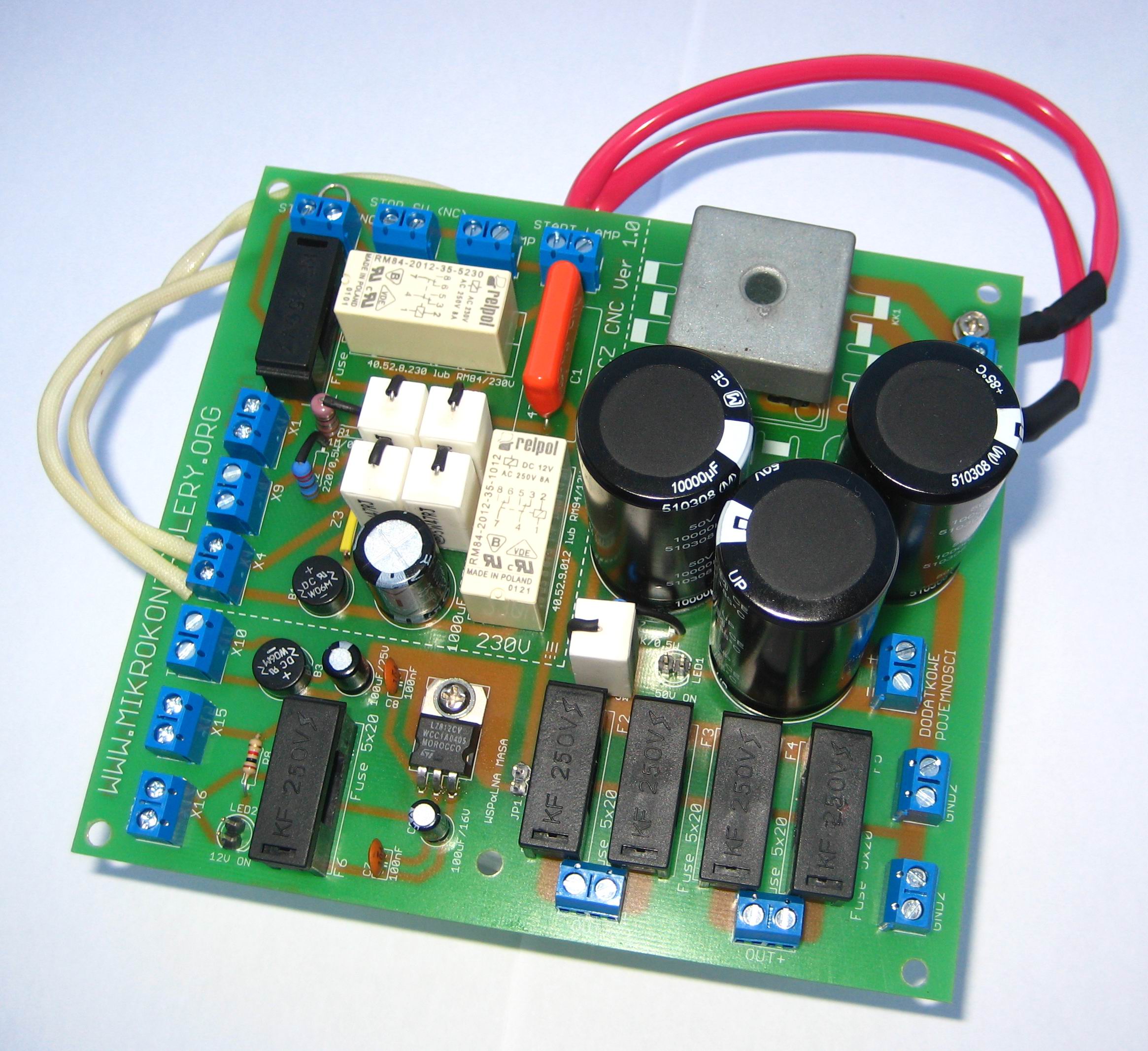
This power supply was made to power the stepper motors in a computer-controlled milling machine. The device consists of start-stop system with signaling status, transformer's soft-start, unstabilized and stabilized power supply with 12V output voltage and ampacity 1A. The power supply was equipped with a number of security features and automatic layout of the capacitors discharges after switching off the power supply.
Unstabilized power supply
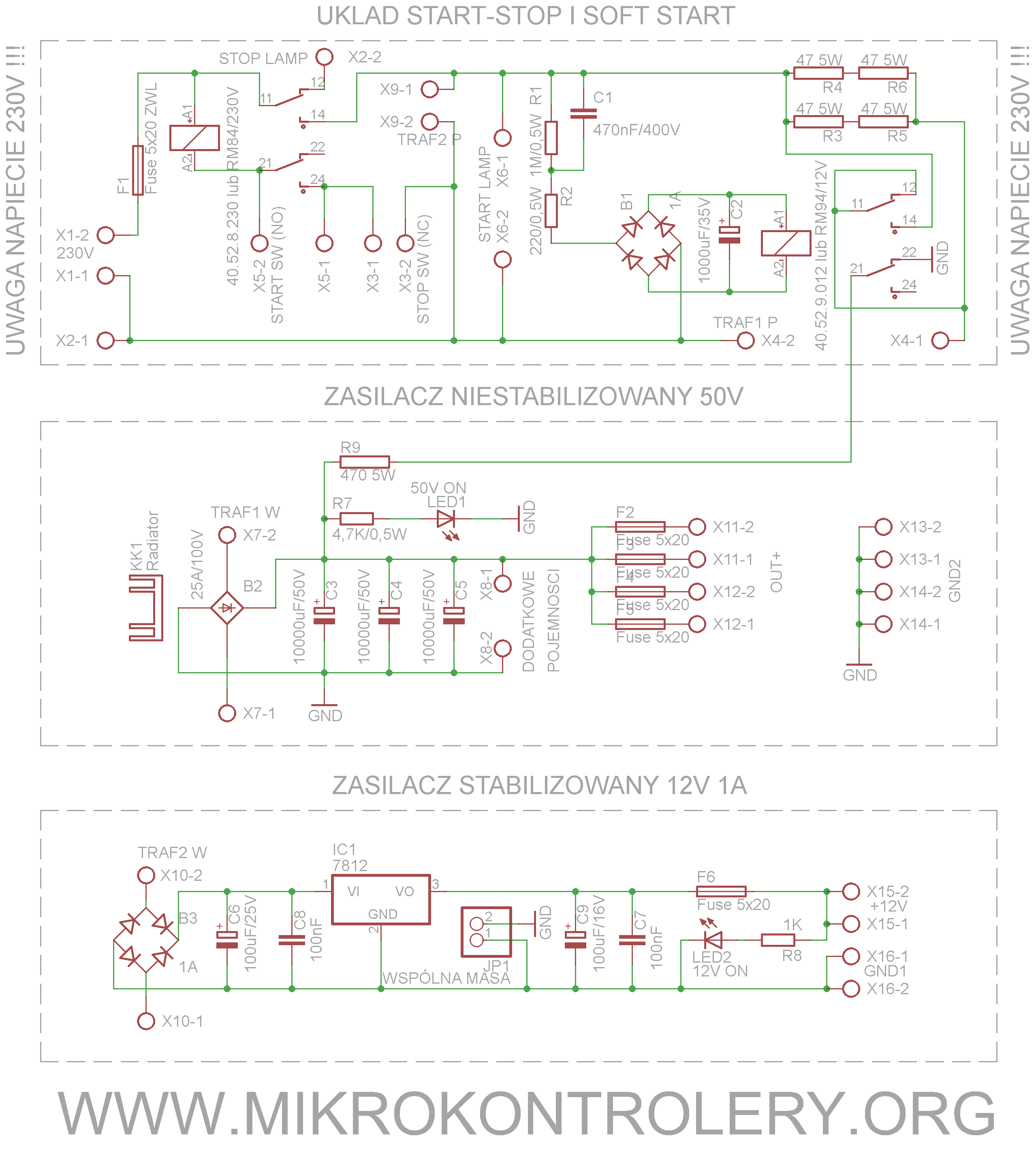
It has 4 blocks responsible for different functions. To ensure an appropriate supply voltage, current efficiency for the stepper motor drivers and to power the logic plate of CNC milling machine, it was necessary to link together in one construction both unstabilized and stabilized power supply. First of them bases on very simple construction. The sinusoidal output voltage of the transformer secondary side is rectified by rectifier bridge B2. Rectified voltage goes straight to the batteries of condensers, which consist of the C3-C5.
If the resultant capacity 30000uF was not sufficient to the terminals marked 'ADDITIONAL CAPACITY', some extra capacitors can be added. They should be connected in parallel with each other, to maintain the proper polarity at the input and that the maximum working voltage of capacitors was not lower than the output voltage of unstabilized power supply. The power supply was designed for a voltage not greater than 50V, that is why the capacitors used were 10000uF/50V. There is also a possibility of changing the output voltage to a higher one, but you must change condensers to work correctly at given voltage. After charging the capacitors and turning off the system without charge at the output terminals OUT1-OUT4 and GND2, the tension can be kept for a long time. This is due to the energy stored in large capacity of the power supply. An accidential short-circuiting of the output terminals would cause a rapid discharge of capacitors, and even damage them. To prevent these undesirable effects, unloading resistor R9 was used. At the moment of turning off the supply voltage is turned on thanks to the contacts of the relay RL2 between output terminals + and – of the unstabilized power supply. It discharges the charge stored in capacitors' batteries. The use of unstabilized power supply was dictated by the regeneration of the supply during braking the stepper motors, which is not allowed in stabilized power supply. The protection of output F2-F5 should be selected in accordance with the load of each output. The project assumed that the three outputs would be charged less than 3A resulting from the stepper motor rated current, that is why 3 fuses and rated current of 3A were used. The fourth output is a reserve and would be used to power the 4 axis of the milling machine.
Stabilized power supply
For the correct operation of CNC milling machine motherboard, especially the relays installed on it, it was necessary to supply the stabilized voltage of 12V. For this purpose, a stabilizes power supply was designed. It was based on the linear stabilizer 7812 and a few passive components. To secure the output of the stabilized power supply, a fuse F6 with rated current of 1A was used.
START-STOP system
The START-STOP system was implemented on the basis of a relay RL1 with two independent contacts. Inputs marked as START SW (NO) and STOP SW (NC) are used to connect the START and STOP buttons of AC adapter. Momentary START button should be NO type (normally open), while the STOP button should be NC type (normally closed). Both momentary buttons should allow operation at alternating voltage of 230V, for this reason, microswitch buttons are absolutely not suitable for this type. More than one button can be connected to terminal STOP SW (NC). This can be for example a limit switch mounted in the housing of the device distribution, so that opening the lid or door of the distribution would result in switching its contacts and immediate power off. Also the emergency stop button can be connected , so called E-stop, which is used in an emergency or equipment failure. All stop buttons must be connected in series. Similarly, the matter is with the START button. Also more than one key that activates the device can be connected. The buttons should be connected in parallel. To the LAMP START and LAMP STOP terminals, indicator lights can be connected to indicate operation on the device (LAMP START) or stop (LAMP STOP). For this purpose, the best choice is the popular 'neon' in green and red. They should be adapted to work with a sinusoidal voltage of 230V, it is not recommended to use LEDs because of the large losses secreted across the resistor current limiting diode.
SOFT START system
Last of described parts of the power supply to the CNC milling machine is SOFT START system. Toroidal transformer of huge power when switching to the power grid, along with a load that is empty capacitor battery can cause unpleasant surprises. Usually it ends with activation of a single fuse or circuit breaker, but in extreme cases it can lead to activation of main security. This is due to transient inrush current of transformer (magnetizing current), which at high transformations can reach considerable values. The solution to main problems used here is soft start system. Primary side of the transformer is powered by 4 high-power resistors R3-R6, which limit the inrush current. Immediately after switching through a transformerless power supply, consisted of a rectifier bridge B1, condenser C1 and resistors R1 and R2, condenser C2 is loaded. After reaching the threshold voltage of the tripping coil RL2, relays 11 and 14 are short-circuited and shunt resistors limiting inrush current, so that the power supply could operate at full capacity. Switching occurs after about 1-2seconds after power – this is the time needed to partially charge the condensers and the magnetization of the toroidal transformer's core, what reduces the peak current. The second pair of contacts 21 and 22 of relay RL2 was used to discharge the capacitors' batteries after powering off the power supply. Resistors R3-R6 shouldn't be less than 5W power due to a very high temporary losses. Vertically mounted resistors should have strictly isolated outputs due to appearing voltage, dangerous to human life and health.
To increase the universality of power supply, a pin connector JP1 with a jumper was used, together described as 'common ground'. It allows to separate unstabilized and stabilized power supply after removing the jumper. It is better to connect the masses (instead of pin connector and jumper, a jumper wire can be soldered), if both power supplies are used in one device.
All power supply outputs are protected by fuses 5x20mm. Rated current of fuses should be chosen according to each output. Also, the whole power supply is protected against overloading, but it should be used a fuse with rated current applied due to the power of transformers. The project uses the main transformer 400VA. As a main precaution, fuse F1 was used with rated current 2A.
ATTENTION! The device contains voltage dangerous for life and human health.


Link to original thread – Zasilacz do frezarki 4 osiowej CNC