Continue to Site

Welcome to EDAboard.com

Welcome to our site! EDAboard.com is an international Electronics Discussion Forum focused on EDA software, circuits, schematics, books, theory, papers, asic, pld, 8051, DSP, Network, RF, Analog Design, PCB, Service Manuals... and a whole lot more! To participate you need to register. Registration is free. Click here to register now.

Power ON 555 motor circuit with Mosfet not relay

Status
Not open for further replies.

rfeyer

Newbie level 5
Newbie level 5
Joined
Mar 9, 2015
Messages
8
Helped
0
Reputation
0
Reaction score
0
Trophy points
1
Activity points
67
Hi All,
I am new to this forum and new to electronics (old in life, though :) ) I started playing with components and schematics about 3 mo ago - please be gentle.

I have a 12vdc 5A source which will supply a 12VDC motor to open a small door.
Then the source is opened (i.e.: the 12VDC) I would like the stream to be intercepted by a 555 timer and Mosfet, allowing a variable (by potentiometer?) 5 to 20 seconds to elapse, then allow current to continue to motor and CONTINUE until original 12VDC is turned off. If the below is anywhere close (partially copied from online and modified) then I would like to add a buzzer as well but will try to figure out placement and resistor values.
So, does it look like the below would do/ handle the task, and, if so, what potentiometer would I purchase?

And again - the current has to stay ON after the time delay

Thanks in advance

<a title="Door Delay.png" href="http://obrazki.elektroda.pl/5323796600_1425925436.png"><img src="http://obrazki.elektroda.pl/5323796600_1425925436_thumb.jpg" alt="Door Delay.png" /></a>
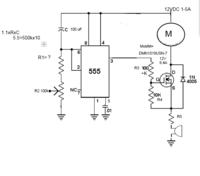


Not sure If I understood the picture linking procedure correctly, hope it worked
 

Could you restate your question, I can't follow it at all. And, apparently, 54 other viewers can't, either. What do you mean "the source is opened"? What do you mean "like the stream to be intercepted"? If you remove power to the motor, aren't you also removing power to the 555? And you don't want that enormous 100K resistor on the gate, I don't think. And you don't want that microphone in line with the source.
 

Could you restate your question, I can't follow it at all. And, apparently, 54 other viewers can't, either. What do you mean "the source is opened"? What do you mean "like the stream to be intercepted"? If you remove power to the motor, aren't you also removing power to the 555? And you don't want that enormous 100K resistor on the gate, I don't think. And you don't want that microphone in line with the source.

TY - will reword:
Current system: A 5VDC signal is initiated from MicroProcessor to a 2 SPDT H-Bridge which allows a 12VDC motor to lower or raise a chicken coop door. The raise and Lower positions have a limiter each which respectively cuts the circuit.

What I would like to add:
a board which DELAYS the current to the motor by 5 seconds or more, during which time a buzzer goes off,
After the delay time, the current should continue to the door to do the job it was asked to do (lower or raise).
When job is done, the limiter (SPDT switch) stops the current to the motor and the normally open portion of the switch returns a signal (being run through a resistor) and tells the Mircoprocessor all is done, then waits to be manually initiated again.

Yes, once the raise and lower limiters cut the current, I wish the current to be cut to the 555

Rainer
 

Since the motor, Mosfet, R5 and the buzzer are all in series then when the Mosfet turns on the buzzer with R5 will get most of the 12V and the motor will get almost nothing.
The output of the 555 can drive up to 200mA and the gate of the Mosfet draws no current. A buzzer usually draws much less than 200mA. Then why not have the 555 drive the gate of the Mosfet PLUS directly drive the buzzer?
 

Hi All,
I am new to this forum and new to electronics (old in life, though :) ) I started playing with components and schematics about 3 mo ago - please be gentle.

I have a 12vdc 5A source which will supply a 12VDC motor to open a small door.
Then the source is opened (i.e.: the 12VDC) I would like the stream to be intercepted by a 555 timer and Mosfet, allowing a variable (by potentiometer?) 5 to 20 seconds to elapse, then allow current to continue to motor and CONTINUE until original 12VDC is turned off. If the below is anywhere close (partially copied from online and modified) then I would like to add a buzzer as well but will try to figure out placement and resistor values.
So, does it look like the below would do/ handle the task, and, if so, what potentiometer would I purchase?

And again - the current has to stay ON after the time delay

Thanks in advance

<a title="Door Delay.png" href="http://obrazki.elektroda.pl/5323796600_1425925436.png"><img src="http://obrazki.elektroda.pl/5323796600_1425925436_thumb.jpg" alt="Door Delay.png" /></a>


Not sure If I understood the picture linking procedure correctly, hope it worked

When you connect 12V output of 555 is high transistor is on and mosfet off, after 5-20 seconds transistor off mosfet on until 12V stops.
Use 12VDC buzzer and put it on the output of 555 and it will buzz for 5-20 seconds.
The mosfet already has a diode inside it, it is better to put a cup to filter spikes.

 
Last edited:

So, essentially split the Mosfet Source to buzzer to ground and motor to ground?
Also, does the rest of the above look like it would work?
 

Hi All,
I am new to this forum and new to electronics (old in life, though :) ) I started playing with components and schematics about 3 mo ago - please be gentle.

I have a 12vdc 5A source which will supply a 12VDC motor to open a small door.
Then the source is opened (i.e.: the 12VDC) I would like the stream to be intercepted by a 555 timer and Mosfet, allowing a variable (by potentiometer?) 5 to 20 seconds to elapse, then allow current to continue to motor and CONTINUE until original 12VDC is turned off. If the below is anywhere close (partially copied from online and modified) then I would like to add a buzzer as well but will try to figure out placement and resistor values.
So, does it look like the below would do/ handle the task, and, if so, what potentiometer would I purchase?

And again - the current has to stay ON after the time delay

Thanks in advance

<a title="Door Delay.png" href="http://obrazki.elektroda.pl/5323796600_1425925436.png"><img src="http://obrazki.elektroda.pl/5323796600_1425925436_thumb.jpg" alt="Door Delay.png" /></a>


Not sure If I understood the picture linking procedure correctly, hope it worked

When you connect 12V output of 555 is high for 5-20 seconds, transistor is on and mosfet off. After 5-20 seconds mosfet is on until 12V is off.
If you connect 12VDC buzzer to the output of 555 it will go off for 5-20 sec.
The mosfet has intrinsic diode, it is better to protect it with a cap.


- - - Updated - - -

Since the motor, Mosfet, R5 and the buzzer are all in series then when the Mosfet turns on the buzzer with R5 will get most of the 12V and the motor will get almost nothing.
The output of the 555 can drive up to 200mA and the gate of the Mosfet draws no current. A buzzer usually draws much less than 200mA. Then why not have the 555 drive the gate of the Mosfet PLUS directly drive the buzzer?

Hi audioguru, I started this forum today, what a small world.
 

You already have a motor controller, so why duplicate it?

Unless I mis-understand, why not intercept the signal from the micro-controller and delay the signal from reaching the existing controller.


---from micro-controller---------------delay circuit------------------motor controller

Some simple logic gates would provide the buzzer signal. Invert the signal after the delay circuit, and with the signal from before the delay circuit feed an AND gate.

TY all for reply
I will change the location of the buzzer to be placed after the 555 output.
However, not trying to re-invent the wheel - would the above schematic work delaying output to motor for 5-20 secs?

TY
Rainer
 

You already have a motor controller, so why duplicate it?

Unless I mis-understand, why not intercept the signal from the micro-controller and delay the signal from reaching the existing controller.


---from micro-controller---------------delay circuit------------------motor controller

Some simple logic gates would provide the buzzer signal. Invert the signal after the delay circuit, and with the signal from before the delay circuit feed an AND gate.

Why not just put the delay in the microcontroller? I don't understand why you would turn something on, and then not want it to turn on for 5 seconds; just wait 5 seconds before you turn it on. Use a second pin to drive your buzzer.
 

The circuit which gives current to the motor is already done, soldered, finished.
The door with motor which receives the current and where the buzzer should be, is 25 feet away from the circuit which produces the current.

Is the above noted circuit possible/ plausible - should it work?
TY in advance,
Rainer

Your circuit will not work, there are 2 critical errors; the mosfet needs 10V in the gate to come on you are driving it with 1V, 555 pin 2 connected to +12V with cap wont start the 555.
 

Hi Moty.
I see a 100 ohm resistor in series with the gate but the resistor has "-K" beneath it. If it is 100K ohms then it would show 100K.

When the capacitor connected to pin 2 on the 555 is charged by the resistors to ground then the pin 2 voltage will drop to its threshold voltage of 1/3rd of the supply voltage then the 555 will be triggered. Since the pin 2 voltage will remain low then the 555 will never time out.
 

Attachments

  • 555 proper timeout.png
    555 proper timeout.png
    79.9 KB · Views: 93

Hi Moty.
I see a 100 ohm resistor in series with the gate but the resistor has "-K" beneath it. If it is 100K ohms then it would show 100K.

When the capacitor connected to pin 2 on the 555 is charged by the resistors to ground then the pin 2 voltage will drop to its threshold voltage of 1/3rd of the supply voltage then the 555 will be triggered. Since the pin 2 voltage will remain low then the 555 will never time out.

Great!
So the changes made by Moti should work since I do want it to stay on after the 5-20 seconds?

Rainer
 

Great!
So the changes made by Moti should work since I do want it to stay on after the 5-20 seconds?

Rainer

Also,

question: What is the purpose of the transistor before the MOSFET gate?

I appreciate everyones input and help!!

Rainer
 

Sorry to be a pain, but I would like to confirm that the resistor/ Potentiometer ratings are correct:


<a title="2015-03-14-Hen Door ddelay-EDABoard.png" href="http://obrazki.elektroda.pl/6264707700_1426344863.png"><img src="http://obrazki.elektroda.pl/6264707700_1426344863_thumb.jpg" alt="2015-03-14-Hen Door ddelay-EDABoard.png" /></a>
 

Status
Not open for further replies.

Part and Inventory Search

Welcome to EDABoard.com

Sponsor

Back
Top