Continue to Site

Welcome to EDAboard.com

Welcome to our site! EDAboard.com is an international Electronics Discussion Forum focused on EDA software, circuits, schematics, books, theory, papers, asic, pld, 8051, DSP, Network, RF, Analog Design, PCB, Service Manuals... and a whole lot more! To participate you need to register. Registration is free. Click here to register now.

power equal to a remote control unit

Status
Not open for further replies.

rajaram04

Advanced Member level 3
Joined
Jun 17, 2012
Messages
871
Helped
6
Reputation
12
Reaction score
5
Trophy points
1,298
Location
earth
Activity points
7,687
Hello sir
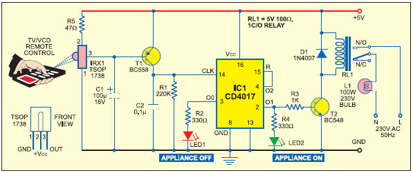
I designed a very simple circuit with a t.v. remote I.R. sensor device , A TRANSITOR , A CAPACITOR etc & its enough able to detect a remote control unit signal form a long distance of atleast 10 metres
no matter which button i am pressing on the unit . .

But only a remote control unit is able to make the circuit trigger not a single IR LED with a single coin cell
I want to make the same power full circuit as a remote control unit is having . . please help
 

A TV remote IR sensor device (I assume you mean the 3-pin kind) only responds to IR modulated at a particular frequency. Typically 36kHz, 38kHz or 40kHz.

Further, most sensors require that the 38kHz (typical) be coded with pulses of limited length.

A 3-pin receiver will not usually respond to steady IR from just a battery and an IR LED (and hopefully a current limiting resistor too).

You can read about some TV remote protocols here:

https://www.sbprojects.com/knowledge/ir/index.php

...and I agree with tpetar, show your circuit(s), so we don't have to guess at what you are talking about.
 
  • Like
Reactions: PA3040

    PA3040

    Points: 2
    Helpful Answer Positive Rating
As Hexreader said, you will need a signal to be transmitted, and that too modulated at around 38KHz.

Unless you want to use a microcontroller, I guess the simplest it can get would be 2 555s running as astables; one at 38KHz, the other at say, 1KHz; connect your IR LED across the outputs of these, and that should be visible to the 3 pin module.

Regards.
 

http://electronics-diy.com/electronic_schematic.php?id=579

REMOTE_CONTROL_RECEIVER.jpg


http://www.circuitdiagram.org/ir-receiver-circuit.html

ir-receiver-circuit.GIF


- - - Updated - - -

http://www.coolcircuit.com/project/8chrem/
http://www.electronics-diy.com/electronic_schematic.php?id=1064
 

https://www.digikey.com/scripts/DkSearch/dksus.dll?WT.z_header=search_go&lang=en&keywords=TSAL6200&x=-1055&y=-51&cur=USDCoin cell has far too high ESR to drive IR LEDs' . As Thickness or length of cell increases, ESR decreases. YOu can verify this with pulse short circuit current.
If you get 1Amp then ESR is 1.5 Ohm , if only if SC current is only 100mA then ESR is 15 Ohms which is the max you should consider but still not as good as Alkaline 1.5V cell which have an ESR of < few ohms.

Small Coin cells have an ESR of > 1kOhm, whereas Alkaline AA cell 1.5V is enough to drive 1 IR LED with ESR of a few ohms. Lithium cell of 2V needs 1- ohm series resistor added as ESR is << 1 Ohm.

IR LED has a threshold of 1V and rises to 1.4 to 1.8V at 100mA max meaning ESR can vary from 4 to 8 OHm depending on device. Consult your specs using VI curve.

Never drive IR LED direct from 5V unless you use 2 or 3 IR LED's in series with R series chosen according to driver drop voltage and power source ESR.

Got it?

If you want to match performance of receiver then your emitter needs to match test spec .
IR diode TSAL6200, IF= 0.4 A, 30 pulses, f = f0, t = 10 ms

If you want to drive 0.4A you must ensure pulse duration of modulated frequency is short. The curve increases ESR after 100mA to 400mA. See spec sheet Figure 4
 
Last edited:

Its not good. You run TSOP on maximum allowed voltage, reduce voltage from 6V to 5V.


Try other transsistor such as NPN 2N2222A.
 

Its not good. You run TSOP on maximum allowed voltage, reduce voltage from 6V to 5V.


Try other transsistor such as NPN 2N2222A.


its only the circuit diagram i got , nothing more than that . . i am still using 5v as supply & a simple L.E.D. at the output . . matter is not all about it . i just want to drive the unit without using a remote control unit from a very long distance as i told this circuit is responding to the remote unit very nicely but i want to design transmitter of my own
 

This receiver TSOP is for 38KHz.


ya it is for 38 khz but how to design transmitter for it ? i mean simple 555 ic can be used ?????
can it be possible to handle it with a long distance such as 10 metre etc ???????

- - - Updated - - -


thanks sir i got what actually we can do . . :)

sir in the diagram of transmitter it is using a coin cell , so please tell how from a coin cell such kind of circuit is driven out ? i mean power is too low to drive but it is driving smoothly . . so how it is ?
 

1st choose your LED and report
2nd choose current pulse 100mA or more? and report
3rd then choose battery and confirm back ( following my advice)

Making clock and driver is easy with NAND gate and transistor for example. and RC timing.
 

Status
Not open for further replies.

Part and Inventory Search

Welcome to EDABoard.com

Sponsor

Back
Top