gres
Full Member level 4


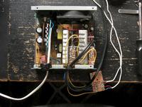
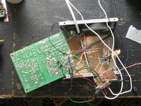
It's a modification of TL494 amplifier http://www.datasheetcatalog.com/datasheets_pdf/T/L/4/9/TL494.shtml
Set errors amplifier to be at low level constantly (sticks 1,2,15,16)
DTC ( 4 stick) polarize by voltage about 0,6V with load by bulb 60W 230V plugged between +24V and -24V; tentatively close DTC ( dead time control) to GDN and then check ouput voltage ( with minimum dead time). While load by 60W 230V bulb, plugged between +24V and -24V should be about +26...27V and meetly -26...27V
-secondary side
Most important is to pay attention on maximum voltages of condensers.
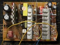
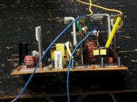
Side (-12V) modify to sample (+12V), that means: remove choke, add 3A fast diodes, reinforce paths at weakest places; might be necessary to rewind main choke if winding (-12V) if make with too thin wire. Condenser 16V can remove from 12V line to 5V line, lines (-12) and (+12) secure by minimum 25V condenser ( better 35V) 1mF
Remove all condensers that connect primary side with secondary. Power supply should be powered with double wires;
Ventilator powered by +10V (5V) through 100...200ohm resistor.
TDA2050 chips, placed on radiators ( about 70x40x3mm), , radiators set at output diodes radiator; pay attention on voltages, at diode radiator is usually (+12V), while on TDA casing, negative voltage of system.


Text comes from http://www.elektroda.pl/rtvforum/topic1447756.html?sid=f785832c4b638d2e7a104725d8c5217a