Continue to Site

Welcome to EDAboard.com

Welcome to our site! EDAboard.com is an international Electronics Discussion Forum focused on EDA software, circuits, schematics, books, theory, papers, asic, pld, 8051, DSP, Network, RF, Analog Design, PCB, Service Manuals... and a whole lot more! To participate you need to register. Registration is free. Click here to register now.

Pool Saltwater Chlorine Generator - PCB Help Needed

Status
Not open for further replies.

Bogey

Newbie level 2
Newbie level 2
Joined
Jul 3, 2019
Messages
2
Helped
0
Reputation
0
Reaction score
0
Trophy points
1
Activity points
58
Hi guys - newbie/first post here. I would definitely consider myself an electronic "hobbyist"; maybe level 3 on a scale of 10. Most of my background is wiring car stereos - which translated to stereos built into coolers to take floating on the river. I did successfully build a radio controlled lawn mower with a couple of deep cycle wheel chair batteries and wheel chair motors and a motor controller (probably the most difficult project I've completed). I've also done a couple projects with relays and a raspberry pi. But I say all that to give you my experience level. There's a lot of very smart people on this forum from the stuff I've read, so please - talk as if you would to a young child :).

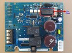
My current project: I have a pool that has a salt water chlorine generator (SWG). It's a Hayward Aquarite model. The PCB model number is GLX-PCB-RITE (Amazon.com PCB). Over the past 6 or 7 years, every time I open the pool for pool season, it seems I have to replace a component on the PCB called the thermistor - inrush current limiter (AS32 2R025) because it constantly burns out. Of course I'm familiar with resistors, capacitors, etc - but I had never heard of this component until this. So I had to do my research and get familiar with them.

The way I understand it, there's two kinds: Negative Temp Coefficient (NTC) and Positive (PTC). The thermistor on my board is NTC.
They are wired in series and have a very high resistance when the current is cold. As the current increases and heats up, resistance value is lowered and allows normal current to flow. PTC just works the opposite - low resistance at cold and higher as temp increases. But like I said, I'm a small level hobbyist, so my terminology or understanding could be wayyyy off.

This is actually a very common issue with this PCB (and other brands as well). So my question is - is there something I can do or replace with to make it more reliable? Or - what I was thinking was to make this part into a quick replacement component on the PCB, somehow....like changing out a blade fuse, instead of constantly disconnecting everything from the PCB, desoldering the old, and soldering the new. Any ideas? I think something like that could work - but I have no clue on the specs, like the gauge the leads would have to be, temp issues, etc.
 

Your understanding of how thermistors work is absolutely correct.

The problem with all thermistors is they have to be hot to do their job and continuous heat tends to shorten their life. I''m not familiar with that product, I rely on adding chlorine chemically to my pool but I like the idea of generating your own chlorine on site. The only remedy I can think of is to switch it out of circuit after it has done its job. I'm guessing it's the black disk "TH1" you are talking about, it looks like it is wired as a surge limiter but without a schematic I can't be certain.

A surge limiter is typically an NTC thermistor in-line with a power feed. Being high resistance when cold, it limits the available current that can flow through it. The heat generated by the current make the resistance drop so it has less limiting effect. The process is self defeating because the lower resistance causes less heat to be produced, it eventually reaches equilibrium. However, the chances are that when the surge period has passed, you could just short it out and consequently increase it's life expectancy. Before explaining how this might be done, I notice there is a relay (black Omron type) next to the thermistor, can you please check whether the normally open and common pins are already wired ACROSS the thermistor. A circuit to bypass the thermistor using the relay contacts may already be present.

Brian.
 

Salt water chlorine generators have to throw a lot of
current to be useful. If that thermistor is in the power
path and is responsible for inrush current limiting, it's
got a hard life ahead of it.

If you can look at the power control electronics and
determine that there's a classical PWM controlling the
voltage or current, you might have an opportunity to
improve the soft-start behavior to the point that the
thermistor can be dispensed with (or maybe, if the
thermistor stands before the input filter cap bank,
replaced with a fat choke to control the input filter
current risetime and peak, less dissipatively).
 

Brian, you were dead on with the relay support of the thermistor. After spending the past few days researching this, it turns out that the board's firmware had a major update. The only versions I've heard of are version r1.50, r1.55, r1.58, and r1.59. Apparently, the relay was added to the board in r1.59, allegedly because of the thermistor failure rate. My version is r1.58 - go figure, lol.

As I said, I researched this over the past few days and came across a very interesting thread on troublefreepool.com. The guy had my plan to create a solution to make the thermistor a quick-change deal, where he used screw terminals soldered into the board. After he got going on the project, he noticed two different boards - one with a K4 relay and one without. And then he gets very technical and I couldn't follow. He posted a number of schematics and says to disregard the K4 relay in the map if your board doesn't have it. Here's the link to the thread: Trouble Free Pool - SWG PCB. I'll post the pics and the schematics below as well.

Now my question is, is there a way to add this relay..and if so, how would I go about doing that? Is that what this person did?
Screenshot 2019-07-05 at 11.43.22 AM.jpg

20180704_184556_e.jpg
SWP15.jpg
AQR Low Voltage Power Supply
AQR Low Voltage Power Supply.jpg
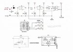
AQR sub-sectional onboard Power Supply Schematic Diagram
Power Distribution_b.jpg

Per the original poster from the board "Here is the missing section of the GLX-PCB-RITE Power Distribution Schematic Diagram to supplement the previous sub-sectional Schematic Diagram I posted above. This concludes the onboard Power Supply Distribution flow path on the board.

The primary function of the SPST K4 Relay is to bypass the Thermistor as described above. Pin# 15 of U5 (MIC5841YN) switches from Hi to Lo state within a few milliseconds after the AC power is turned on. Pin 15 remains Lo until the AC power is turned off. Disregard, the K4 from the drawing if your board does not have it!

OTOH, pin# 15 on the older AQR mainboard has no circuit trace and the output is not assigned. The Micro-Controller chip dictates the switching functions of U5. Presumably, a burned-in Flash and not sure if something my outdated programmer can read. For the skilled tech-savvy, a simple timer would do the trick when upgrading the board."
Pwr Dist Section-cell.jpg
 

I'm not sure how the later revision board/firmware knows when to short out the thermistor but I assume it senses the voltage across TH1 through the current sense circuit then when it is low enough (indicating it is hot) it drives U5 pin 15 low to operate the relay. That would decide the exact 'few milliseconds' you mention above. The voltages/currents involved are far too high for an MCU to handle by itself so there must be some interfacing components between it and the relays.

Possibly the thermistor is in some way regulating the current through the salt cell so the relay may open and close according to needs rather than just operating at timed periods, however to sense the current it would have to open the relay occasionally or it would only close once and sense nothing thereafter.

A wild guess - you could close the relay on a timer, maybe set to 30 seconds or so, given the thermistor construction I would would think it would reach operating temperature in less than 15 seconds so I'm allowing some overhead to be sure. Wiring a relay across it with a simple timer circuit would be worth a try and inexpensive to construct. I assume that as it is, the thermistor stays hot all the time so anything that reduces that time will help.

The more scientific way would be to add a fixed resistor in series with the thermistor and sense the voltage across it to operate the relay. That would be more like the way the later revision boards do it and it would allow for constant monitoring. The fixed resistor would have a low value so it generated little heat in itself. The circuitry would be quite a bit more complicated though.

Brian.
 

Status
Not open for further replies.

Part and Inventory Search

Welcome to EDABoard.com

Sponsor

Back
Top