Continue to Site

Welcome to EDAboard.com

Welcome to our site! EDAboard.com is an international Electronics Discussion Forum focused on EDA software, circuits, schematics, books, theory, papers, asic, pld, 8051, DSP, Network, RF, Analog Design, PCB, Service Manuals... and a whole lot more! To participate you need to register. Registration is free. Click here to register now.

[SOLVED] PMOS circuit works but does not turn off completely.

Status
Not open for further replies.

oahmad

Newbie level 5
Newbie level 5
Joined
Aug 17, 2010
Messages
8
Helped
1
Reputation
2
Reaction score
1
Trophy points
1,283
Location
us
Activity points
1,370
Hi Guys,
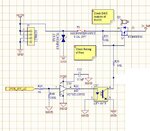
Attached is my circuit.

pwrCircuitPMOS.JPG

The way it is intended to work is as follows:

The Mosfet is supposed to be off via the pullup R21=10K
When the PWR_SW_uC line is High, it is supposed to turn on the diode on the optoisoaltor turning on the optoisolator transistor which pulls down R33=14K. Due to the divider from 24VDC and R21 and R33, the Gate of the PMOS Q2 is pulled to 14V which turns on the PMOS. The divider is there to prevent the gate from going lower than the source to less than 16V (according to the datasheet).


So it turns on OK. I am having trouble keeping the PMOS off. The gate of the PMOS is around 18VDC. I disconnected the Optoisolator by lifting the Collector to make sure it wasn't the culprit and have ruled it out. Basically the pullup is not working as-is. I tried a lower value pullup (Changed R21 to 1K and R33 to 1.4K), and brought the gate to around 20VDC...not fully off still.


Can someone please help?

Thanks!
 

Please define the meaning of "not turn off completely", what have you connected to the output and how much current do you get

Alex

P.S. the drain source of your mosfet are reversed, the arrow pin is the source
 

It looks like there are aditional connections to the gate node which
you have cropped out. Something is imposing 6V across 10Kohms
evidently.

Large MOSFETs do not have zero leakage even at zero Vgs. You
may have to apply a resistive load to ensure that the output of
the PMOS switch goes "close enough" to ground when off. It
may require mA when on, to ensure that "off" is below the
level that makes the driven load acceptably de-energized.
 

I disconnected the part of the circuit that was 'cropped out', so it is not a factor.

---------- Post added at 22:47 ---------- Previous post was at 22:42 ----------

Right now, I nominally consume around 229mA at 24VDC; gate is at 14.39VDC (WOrks as designed).
When off, the current drops to around 120mA; the gate is at 17.8VDC. (SHOULD BE 24VDC at teh gate)
 

Hi there again.
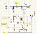
I did some investigation and have an updated and expanded schematic that shows all the players involved in a consolidated form how it is hooked up currently. I still have that same issue and I now it is being caused by U30. The Drain and Source are NOT switch contrary to the symbol on Q2. I'm looking for a solution to the issue. Let me explain the circuit again in more detailed as to what I'm trying to accomplish.

SoftPwrII.JPG

Power (24VDC) comes to the circuit through J7; TVS7, F1 are protection devices and onto the Source of Q2. R21 forces the gate of Q2 to be high and therefore Q2 is off to begin with. At some point, the user shorts the net PWR_SW to GND which momentarily turns on Q2, which then feeds 24_Safe to the rest of the circuit that includes a microcontroller that then sets pin PWR_SW_uC high, turning U17 on and pulling the Gate of Q2 Low through R14********so far everything works as designed********** So I now need to detect when the user will short PWR_SW to GND again signifying that they want to shut down the circuit. For this I have hooked up U30 as shown such that when PWR_SW is shorted to GND again, The output of U9 will ideally momentarily go low that will trigger an interrupt on the micro-controller to allow it to set the PWR_SW_uC LOW, thereby, ideally, turning off U17 and the gate Q2. The Diode D1 is there so that while the PWR_SW_uC is low, I still need the PWR_SW line to be high to detect the high->Low Transition.

So actually happens is that after the external interrupt occurs, the uC sets PWR_SW_uC low and the voltage at U17 pin 4 goes from 0VDC to around 6VDC. When I disconnect R14, (and so U30) everything shuts off as designed.

Can anyone suggest a way to detect the H->L transition on PWR_SW while allowing the Q2 to turn off?

Thanks!
 

I was able to solve this problem. Thanks to everyone for attempting to help!
 

It would be useful to share the cause of the problem with the rest of us, this could help other members to avoid a similar mistake.

Alex
 

Hi Alex.

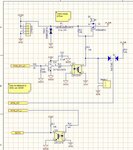
That is a good point. Here is a snapshot of the schematic that works. This circuit is an isolated version of a soft-power switch that utilizes a PMOS. SoftPwrIII.JPG

Note again that the Q2 schematic is correct with respect to source and drain...the S, D on the little physical representation is wrong.

An explanation:

At Reset, the PMOS Q2 is off. When PWR_SW and PWR_SW_2 are connected together (maybe through a button), the gate of the pmos is pulled momentarily lower than the threshold of the PMOS Q2 and turns it on, which supplies power to the rest of the circuit. A Micro-controller can then set PWR_SW_uC high to hold the PMOS Q2 on for when the button is released.

When the button is pressed to short PWR_SW, PWR_SW_2 again, current flows (just as it did on reset) to set EINT0 Low through the optoisolator, which is connected to the processor's External Interrupt pin. This initiates the power-down cycle, which also sets PWR_SW_uC low along with other house-keeping tasks.

D1 is necessary to allow the common-cathode node to the optoisolator to be high regardless of the state of the anodes...especially when the left-diode anode is low due to PWR_SW_uC.

Header2 allows for overriding the power to the circuit and maintaining power to the whole circuit: this can be utilized, for example, when the micro-controller is being flashed with new firmware.

I also discovered that R48 needs to be a lower value around 5.1K; 100K is too weak of a pull-down.

Hope this helps someone who is looking to incorporate an isolated 'soft-power' switch. I don't take any responsibility for its correct operation or fitness of use for a particular purpose and any ensuing damage. Please use this at your own risk.

Thanks!
 
Status
Not open for further replies.

Part and Inventory Search

Welcome to EDABoard.com

Sponsor

Back
Top