Continue to Site

Welcome to EDAboard.com

Welcome to our site! EDAboard.com is an international Electronics Discussion Forum focused on EDA software, circuits, schematics, books, theory, papers, asic, pld, 8051, DSP, Network, RF, Analog Design, PCB, Service Manuals... and a whole lot more! To participate you need to register. Registration is free. Click here to register now.

Plugging home-made oscillators into computer sound card

Status
Not open for further replies.

nathaniel

Newbie level 3
Newbie level 3
Joined
Dec 23, 2011
Messages
3
Helped
0
Reputation
0
Reaction score
0
Trophy points
1,281
Activity points
1,327
Hi all

I'm just starting out with electronics as a hobby. One of the main things I want to do is build noise-making circuits (e.g. audio-frequency oscillators) whose output I will record using my computer. I want to experiment a lot with circuit design (I have plenty of theoretical background, I just don't have much practical experience), but I don't want to risk damaging my computer's sound card - or at least, I want to minimise that risk as much as possible.

I've found various circuit designs that include line-level outputs, but what I can't seem to find is general advice on connecting home-made circuits to computer sound cards. Specifically: what voltage range should the signal have? How much resistance will the line-in port have? How much risk is there of damaging the sound card (e.g. if I stick to battery powered circuits will I be safe, or will accidentally plugging 9 volts of DC into my sound card kill it?) and what can I do to minimise any risk? For example, is there something I can buy or build to limit the voltage and current to safe levels, or isolate it so that if I accidentally connect it to my power supply I'll blow my home-made circuit instead of my sound card? Also, what (if anything) would I need to do differently to connect a circuit to headphones rather than my computer?

If anyone can answer these questions, or give me some more general advice, or point me to some kind of how-to document for this sort of thing, I'll be very grateful.
 

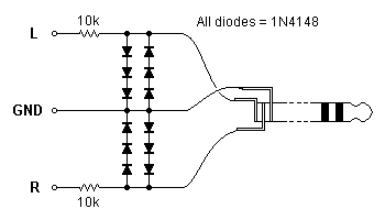
This circuit will protect your sound card against pretty much anything short of a lightning bolt.

44_1324719759.png


It clamps the input level at about +/-1.8V which will not damage your sound card. Higher signal levels will sound distorted due to the clamping action. This circuit is intended for the Line input (blue socket).
 
Many thanks to both of you. Pjdd's circuit in particular is really helpful. Is there somewhere I can find more information on this technique? In particular I'm wondering about the purpose of having several diodes in serial. (Does it reduce the distortion when the signal isn't clipping, or provide extra protection, or both?) I'm also wondering whether I could safely replace the 10k resistors with potentiometers in order to create a gain control - I guess I'm sometimes going to want to record quite low voltage signals and sometimes quite high ones, depending on the circuit I'm playing with, so building this into a little box with a volume knob would be a really handy little project.
 

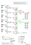
Very simple passive mixer for PC line in.
You can add channels for your needs.......

PassMixer_PC_LineCard_.jpg

PS.
Did you know that you can test and listen to different wave forms
without the oscillator construction, for ex. look here.........

Wolfram|Alpha Examples - Audio Waveforms

I made two examples....
play sin (1500 t )+ 1/3* sin(3*1500 t )+ 1/5* sin(5*1500 t )+ 1/7* sin(7*1500 t ) ) - Wolfram|Alpha
play sin (1500 t )+ 1/2* sin(2*1500 t )+ 1/3* sin(3*1500 t )+ 1/4* sin(4*1500 t )+ 1/5* sin(5*1500 t ) ) - Wolfram|Alpha

general info about music, notes, chords, sound .......

music - Wolfram|Alpha
 
Last edited:
Is there somewhere I can find more information on this technique?
Search for limiting or clipping circuits.

... I'm wondering about the purpose of having several diodes in serial.
The input signal will be unaffected until its peak to peak amplitude reaches the sum of three diode forward voltages, i.e. approximately 1.8V. The diodes will then begin to conduct and prevent the signal from further increase. (I would have thought that your plenty of theoretical background would have included this.)

(Does it reduce the distortion when the signal isn't clipping, or provide extra protection, or both?)
Neither. It simply sets the maximum signal amplitude which can be applied to the protected device - in this case your sound card)

I'm also wondering whether I could safely replace the 10k resistors with potentiometers in order to create a gain control ...
No, that wouldn't work. You could , though, put a potentiometer across the input of the circuit which Pjdd provided.
And don't forget, that for very weak signals, you will have a Microphone input to the card too. It's much more sensitive than the Line input. But it would be advisable to use a limiter, similar to the one already presented, at the Mic input as well. In which case you could reduce the number of diodes in each of the two legs (the Mic input is mono) to just one, and perhaps use Schottky ones instead - they have a lower forward voltage.
 
I see that others have posted replies while I was away from my computer (Christmas festivities, you know). Since I'd already typed much of the answers below, I'll post them anyway.

Many thanks to both of you. Pjdd's circuit in particular is really helpful. Is there somewhere I can find more information on this technique?
I just made up this exact design after reading your post without referring to any other source, but the principle of using diodes to clamp a signal is well known. So you should be able to find useful references if you search with a parameter like "diode clamp".

In particular I'm wondering about the purpose of having several diodes in serial. (Does it reduce the distortion when the signal isn't clipping, or provide extra protection, or both?)
The diodes are there to protect the input of your sound card. They do not prevent distortion. In fact, they cause distortion when the input signal is above a certain threshold.

We're making use of a silicon diode's non-linear characteristics here. A diode passes very little current even in the forward direction until a certain breakover voltage is reached. Therefore, at input voltages of up to a few hundred millivolts peak, it's as if the diodes are not there at all. That is, the diodes act approximately like an open circuit.

When the input signal reaches an amplitude high enough to make the diodes conduct, their AC impedance decreases quickly so that a part of the signal is dropped in the 10k series resistors. Even if we keep increasing the signal voltage, the diodes' dynamic impedance decreases further so that the voltage across the diodes rises only by a small amount. In other words, the input voltage to the sound card is clamped.

The clamped voltage is around 0.5-0.6V per diode depending on the amplitude of the external input signal. Three diodes in series limit the output to the sound card at about 1.5-1.8V peak. Two sets of 3 diodes each are paired in opposite polarity for each channel so that the incoming signal is clamped for both positive and negative swings.

I'm also wondering whether I could safely replace the 10k resistors with potentiometers in order to create a gain control - I guess I'm sometimes going to want to record quite low voltage signals and sometimes quite high ones, depending on the circuit I'm playing with, so building this into a little box with a volume knob would be a really handy little project.
It will be better if you leave the 10k resistors as they are and place a potentiometer configured as a volume control in front of them, that is, where the external signal comes in.
 
Hi all

Thanks again, this is all very helpful. I just want to clarify the comment about distortion - I understand the way the circuit functions, but I was concerned that because, for a diode, I≈ISexp(V/VT) (with VT the "thermal voltage", around 25 mV at room temperature, and IS a property of the diode), the circuit would introduce a little bit of distortion at even low amplitudes, and I thought maybe the multiple series diodes were to mitigate that. However, applying the exponential diode formula to your circuit, I get VIN = Vout+RIS(exp(Vout/3VT)-exp(-Vout/3VT)) (with R being the 10k resistor) - if I guess a value for IS of around 10-10 and plot this, it looks like this:

Screen shot 2011-12-26 at 19.25.59.png

which is very linear indeed until the magnitude of Vin is around 1 volt - so I guess distortion won't be an issue unless I overdrive it on purpose :)

@Syncopator, sadly Apple in their wisdom saw fit not to provide me with a mic input - though buying an external sound card with one seems like an option for recording small signals. Or I could just make an amplifier. Regarding the point about my background, I have a lot of knowledge about physics and dynamical systems theory and quite a bit about music production and synthesis techniques, so I'm fairly confident in my ability to design novel sound-producing circuits once I get going - but in terms of electronics per se I'm more or less a total noob - sorry for not making that clearer.
 

One of the pitfalls of trying to contribute in a forum is that it's difficult to judge the level of an OP's background knowledge. As someone else said not long ago, we have to balance the two opposite risks of either going over the OP's head or insulting him by dwelling on things he already knows well.

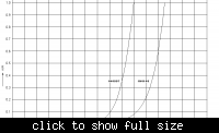
Indeed, the purpose of using 3 diodes in series instead of just one is to raise the level at which clipping starts. In that sense, yes, the aim is to reduce distortion. Below is a composite graph of the V-I characteristic curves of two real diodes that I plotted by actual measurements ages ago. You can compare them to the results obtained with your theoretical model.


It's nice to have someone with a solid background in physics take an interest in electronics. A word to the wise though: Practical electronics, particularly analog, can be very tricky. I often see some beginners approach it as they would the task of assembling some modular units and cobbling them together. It just doesn't work that way most of the time. The interaction between various components is often much more intricate and subtle than in, say, assembling a computer or a car from available building blocks.
 

Status
Not open for further replies.

Part and Inventory Search

Welcome to EDABoard.com

Sponsor

Back
Top