Continue to Site

Welcome to EDAboard.com

Welcome to our site! EDAboard.com is an international Electronics Discussion Forum focused on EDA software, circuits, schematics, books, theory, papers, asic, pld, 8051, DSP, Network, RF, Analog Design, PCB, Service Manuals... and a whole lot more! To participate you need to register. Registration is free. Click here to register now.

[SOLVED] PLL and LCD: LCD shows garbage while PLL is used

Status
Not open for further replies.

Mithun_K_Das

Advanced Member level 3
Joined
Apr 24, 2010
Messages
899
Helped
24
Reputation
48
Reaction score
27
Trophy points
1,318
Location
Dhaka, Bangladesh, Bangladesh
Visit site
Activity points
8,254
If there is no PLL used, then display is ok. But when PLL is used LCD starts showing garbage.
In this case what technique should be used to maintain the LCD operation?

MCU:dsPIC30F2010;
X-Tal:7.5MHz.
PLL: x16;
Max Freq: 120MHz.
LCD: 16X2;
Compiler: mikroC pro for dsPIC.​
 

Likewise but I wonder if the PLL in question is the internal clock multiplier. It would be useful to have some more information.
If it is the internal multiplier, the chances are the timing signals are too fast for the LCD to respond to. The usual delays in the program would have to be recalculated using the multiplied frequency rather than the input clock frequency.

Brian.
 

Hi,

I will be waiting for Klaus to respond to this one with his usual wit.
Here I am.

Yes, I agree with Brian: timing problem.
But without useful informations..all we can do is guessing.
No information about
* code
* display type
* connections
* wiring, wire length
* power supplies
* logic levels...

Klaus
 

Zip and post the complete mikroC PRO dsPIC project so that the Oscillator settings could be examined.

In mikroC projects the oscillator settings are done in Project > Edit Project... dialog box and not in the code.
 

As I found, any simple code with LCD and dsPIC30F2010 have this issue. I've completed few projects recently with dsPIC. when the oscillator is selected as HS and using a 20MHz crystal, it is ok to run the code and the LCD(16X2).

51jy8enJluL._SX425_.jpg

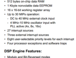
But to get a good result, the oscillation should be used by multiplying using PLL (x16) keeping the oscillator 7.5MHz in circuit. So that the maximum frequency of dsPIC30F2010 can be achieved.

1.PNG

Even if I use 40MHz crystal without PLL multiplication both in code & circuit, LCD shows garbage value. Seems like timing issue. I have no proteus library for dsPIC30F2010, so that I can not draw the circuit in proteus. But any circuit works in this same way. There is a solution of course. Because, I've checked some designs where they are using 6.144MHz crystal but using very fast timing and response is high which is not possible without using PLL (x16).

- - - Updated - - -

Hi,


Here I am.

Yes, I agree with Brian: timing problem.
But without useful informations..all we can do is guessing.
No information about
* code
* display type
* connections
* wiring, wire length
* power supplies
* logic levels...

Klaus

Code: Any simple code with LCD have this issue.
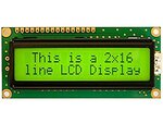
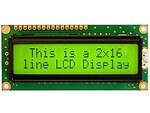
Display type: Standard HD44780 LCD, 51jy8enJluL._SX425_.jpg
Connections: as I do not have the library file for dsPIC30F2010 so I can not draw the diagram but any working circuit have same issue.
Wiring: PCB, length: <6cm
Power: 5V DC, 1.5A ripple: <0.001v
Logic Level: 5V digital logic.

It seems like timing issue with LCD.

- - - Updated - - -

Likewise but I wonder if the PLL in question is the internal clock multiplier. It would be useful to have some more information.
If it is the internal multiplier, the chances are the timing signals are too fast for the LCD to respond to. The usual delays in the program would have to be recalculated using the multiplied frequency rather than the input clock frequency.

Brian.

I found one solution using a shift register to drive the LCD and 2/3 wires connection to send the commands to shift register from MCU. But that increases the parts number. I found some designs where they are not using any shift registers but using PLL to get fast response. One point I found that they are not writing any information on the LCD instantly, letters or symbols are being printed serially. That means, if I want to display "Text" on the LCD, they are printing like "T" (20-50ms gap),"e" (20-50ms gap),"x" (20-50ms gap),"t".

So what can we get from this clue?
 

Hi,

Alert! Stop reading here, if you can't stand the truth.
********

Come on!
If you want us to help, you need to useful informations first!

Sorry for my honest words: Not showing your code is laziness. Copy and paste just takes 2 seconds.
And not spending this time ... will not motify forum members to spend much time, too.

As I found, any simple code with LCD and dsPIC30F2010 have this issue
Surely not.
I still think it's a timing problem. And every code can adjust for timing.
Every LCD datasheet shows the timing diagram.
For example the minimum pulse length of the "E" signal.
(Pseudo code)
...
E = HIGH
E = LOW
...
may work for slow microcontrollers only
For faster ones you may use
...
E = HIGH
NOP
NOP
NOP
E = LOW
...
OR
...
E = HIGH
DELAY_US(x)
E = LOW
...
may be used.

But any circuit works in this same way
Surely not. Some use SPI, I2C, 4bit parallel, 8 bit parallel, unidirectional, bidirectional...some use external circuitry, others not.
--> RTFM

Connections: as I do not have the library file for dsPIC30F2010 so I can not draw the diagram
Nonsense. All you need is a sheet of paper and a pencil.

they are printing like "T" (20-50ms gap),"e" (20-50ms gap),"x" (20-50ms gap),"t".
Also nonsense.
RTFM helps. The gap between each character is specified, and it's usually more than 1000 times faster than your "20ms" timing,

My recommendation:
* stop designing electronis in "trial and fail" manner.
* read datasheets
* draw schematics (hand drawn is O.K.)
* keep on the datasheet specifications
* do calculations (like timing according microcontroller clock frequency)
* then write or modify code.

Klaus
 

At least you could have posted the LCD connections to dsPIC so that I could have written a sample LCD test code in mikroC PRO dsPIC. For simple LCD test code, even the demo version of mikroC PRO dsPIC can be used and more people could have helped you.

What is the use of showing the LCD front picture? The partname of the LCDs like JHD1602A, etc,... are always printed on the backside of the LCD. You could have posted that to get your issue solved quickly.
 

Hello Mithun_K_Das,

I´ve recognized you reported my post as "rude".
This was not my intention. I apologise for this.
It was not meant as a personal offence. It was meant as help to reduce the time to get a reliable solution to your problem.

I tried to show you a fast way how to get a reliably working design. From the scratch.
This is my way of designing electronics. My industrial designs usually work for more than 10 years 24/7 without a single RESET.
Measurement circuit that measure down to 100pA up to current control loops for several 1000A and Megawatts.

My way. For sure you are free to choose your own way.

My way.... I know my discussion style is not very diplomatic. It is not people oriented, but technical oriented.
So you are free to ignore my posts, or add me to your "forum member ignore list", or on your request I will stop responding to your posts.

Again: Please don't take my posts as personal offense, take them as assistance to find reliable technical solutions.

All the bset for you.

Klaus
 

Status
Not open for further replies.

Similar threads

Part and Inventory Search

Welcome to EDABoard.com

Sponsor

Back
Top