Continue to Site

Welcome to EDAboard.com

Welcome to our site! EDAboard.com is an international Electronics Discussion Forum focused on EDA software, circuits, schematics, books, theory, papers, asic, pld, 8051, DSP, Network, RF, Analog Design, PCB, Service Manuals... and a whole lot more! To participate you need to register. Registration is free. Click here to register now.

Please suggest BJTsor FET for 5GHz oscillator (negative feedback).

Status
Not open for further replies.

Terminator3

Advanced Member level 3
Joined
Feb 25, 2012
Messages
802
Helped
71
Reputation
142
Reaction score
63
Trophy points
1,308
Activity points
9,027
I am trying to design 5GHz oscillator. I am currently calculate stability and reflection coefficients for BFP420 and NE3210S01. Problem is BFP420 is too stable for series feedback. And NE3210S01 have too much gain, and have unstability problems at higher frequencies. So i am searching for some "unstable" transistor with less gain than NE3210S01, but more unstable than BFP420.
 

I used BFP420 at 5GHz in Negative Resistance configuration, which works better than feedback configurations (at least in this case).
Have to spend some time choosing the right bias point and tuning the resonator for the right frequency range.

 
Thank for your reply! I managed to make BFP420 unstable by adding gate open stub (common gate configuration). Although i use H-biasing scheme with 4 resistors now, but Vce is similar to S53MV's VCO. Now i am trying to calculate push-push oscillator. Actually it goes well. But there is one thing that i can't understand: how 180 degree anti-phase operation is obtained. Here is an example of push-push oscillator (it is balanced oscillator, but can be used as push-push).
http://www.taconic-add.com/en/pdf/technicalarticles--antiphase_design_for_balanced-oscillators.pdf
and here is radar-detector with some information on common resonator push-push oscillator.
http://www.freepatentsonline.com/5402087.html
the length of said microstrip resonator at each side of said output tap is at least one-quarter the wavelength of the oscillating frequency of the respective one of the said pair of transistors to which it is connected plus a sufficient extra length so as to provide a capacitive impedance at the oscillating frequency of each respective transistor
I can't understand between which points 180 degree phase shift is measured. Don't we added additional length to provide capacitive impedance? It now maybe 190 or 200 deg. But in reality it is not. Somehow virtual ground remains in the center of line. I can't understand why virtual ground will be in the center of the common resonator.

I can't understand how to go from one 5GHz building block to push-push with common resonator.
For example, i calculated required Gsource and some inductance to realize it.
It can be realized by open-stub or (short-stub +180 deg).

Because 10GHz push-push will have virtual ground at center, i must
1) decrease single 5GHz oscillator stub length by 90 deg and put them together. Idea is that single 5GHz oscillator have short located at 90 deg from open stub length.
2) or remove short in short stub and connect two oscillators together
But it seems something is wrong with calculations.
Single oscillator is around 5GHz, but when i connect them using this approach, frequency shifts too significantly (5GHz becomes 4GHz to 6GHz). Harmonic output is good (8-12GHz).

So my current problem is i want make push-push frequency right by calculations, not by tuning.
 
Last edited:

I used BFP420 at 5GHz in Negative Resistance configuration, which works better than feedback configurations (at least in this case).
Have to spend some time choosing the right bias point and tuning the resonator for the right frequency range.


Did that circuit really work without feedback ? It uses definitely internal C-E or C-B Miller capacitances to provide the oscillation conditions at that frequency but these capacitances are really bias depended and they shift very quickly by ambient temperature that is not desired.They can also create multi resonant points and the oscillator may tremble.
Interesting circuit for 5GHz..
 
Currently i am in calculations stage. Choosed Gsource, Gload, inductive stub on base. Instability is easy to obtain. I tried simulate it a little in push-push configuration, but i have some question:

With single 5GHz oscillator LO level is about 15dBm, second harmonic around 3dBm
With two 5GHz oscillators in push-push configuration, second harmonic output is only 0dBm, while first and all odd harmonics disappeared. I have concerns about 10GHz harmonic output of push-push oscillator. I expected more. Although good thing is that odd harmonics totally cleared out.

What harmonic output i should expect in each case?
Actually single diode multiplier shows more output at double frequency, but also too many other harmonics.
 
Last edited:

Cancellation of even harmonics is expectable in symmetrical push-pull, reduction of odd harmonics not generally.

The necessary balun might dwart the even harmonics suppression if not designed correctly.
 
mine configuration is symmetrical push-push, so odd harmonics are in anti-phase relation, even harmonics are in-phase. Currently i use this method: single oscillator designed with Rload = 0 Ohm (short circuit). Then i take two identical oscillators, remove short circuit and connect them in that point through tee-divider, where F0 sum is always null, and 2*F0 is in-phase sum.
 

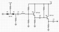
The negative resistance VCO that I posted above it will work fine at 5 GHz, and if you spend some time in tuning and use high quality components and PCB layout, it will work even at 10GHz.
This approach is cheaper than a push-push topology, and the VCO slope MHz/Volt would be much linear, which is very important when designing an FMCW radar.

 
I considered 10GHz oscillator. But at this frequency PLL or prescaler would be more expensive, than using additional BJT at 5GHz. I still did not decided which one to use. My main concern is precise center frequency (at least +-1MHz precision) to meet 10.5-10.55 GHz (sweep less than 50MHz).
For example: https://www.ntia.doc.gov/legacy/osmhome/alloctbl/allocghz.html
At 5GHz it can be easily done using prescalers from cheapest ADF PLLs (using only prescaler output, PLL is off).
Another approach is using direct 10GHz oscillator, similar to your schematic, but with additional a little less than~10GHz DRO reference oscillator, which will provide difference output of <1GHz, which can be divided with very cheap prescaler. DRO reference oscillator + 3GHz /256 prescaler is cheaper than PLL / divider for 10GHz.
 

vfone, can you please confirm biasing resistor values on your schematic? (for oscilaltor BFP420).
R1=3300 [Ohm] (upper)
R2=3300 [Ohm]
Rcollector=0 [Ohm] (none)
Remitter=180 [Ohm]
Text on your schematic image looks a little blurry.
I reverse-calculated biasing:
R1=3300
R1 = 3300
R2=3300
R2 = 3300
Rc=0
Rc = 0
R_e=180
R_e = 180


Vcc=5
Vcc = 5

Vb=(R2/(R1+R2))*Vcc
Vb = 2.5

' Vb=Vbe+Ve

Ve=Vb-Vbe
Ve = 1.8

' Re=Ve/Ic

Ic=Ve/R_e;

' Ic [mA]
Ic*1000
Ans = 10

' Vcc=Vce+Ic(Rc +Re)

Vce=Vcc-Ic*(Rc+R_e)
Vce = 3.2

Which gives biasing in your schematic:
Vce = 3.2 v
Ic = 10 mA

While S53MV's oscillator using same transistor uses
Vce ~ 4 v
Ic ~ 15 mA

wich is nearer to Vce breakdown of 4.5v
collector current absolute maximum rating is 60 mA

can you give some hint on how you choose Ic and Vce for your oscillator?
 

Yes, the values are correct. Usually I prefer to use a bit smaller DC collector current for BJT oscillators, especially for VCOs.
Most of the situations this would improve phase noise, frequency stability, MHz/V linearity, and give less harmonics.
 
What is purpose of second transistor in your schematic?
Just amplification? Can it work as buffer amplifier against load variations?
 

Second transistor is a buffer, is not an amplifier. If you want to add an amplifier better is to put after, and let the buffer in place. This would improve many of the performances of the VCO.
 
Status
Not open for further replies.

Part and Inventory Search

Welcome to EDABoard.com

Sponsor

Back
Top