Continue to Site

Welcome to EDAboard.com

Welcome to our site! EDAboard.com is an international Electronics Discussion Forum focused on EDA software, circuits, schematics, books, theory, papers, asic, pld, 8051, DSP, Network, RF, Analog Design, PCB, Service Manuals... and a whole lot more! To participate you need to register. Registration is free. Click here to register now.

[SOLVED] pic18f2550 with mikrobasic

Status
Not open for further replies.

jerryd

Member level 2
Member level 2
Joined
Feb 4, 2013
Messages
48
Helped
0
Reputation
0
Reaction score
0
Trophy points
1,286
Activity points
1,709
edaboard,
I'm using a pic18f2550 and have a Micro C program that plays well with the
hardware. I use the 2550 because it has the exact number of I/O ports and
interrupts needed.

Now I'm trying to write the same program in mikrobasic using the same hardware.
I started with a simple light an led but can't get the pic to do anything.

Here's the code:
program NewMatch

' Declarations section

main:
INTCON = 0x00 ' Disable all interrupts
OSCCON = %01110010 ' Select 8MHz oscillator

ADCON0 = 0x00 ' Turn off ADC
ADCON1 = 0 ' Disable Analog functions

PORTA = 0x00
TRISA = 0x00
TRISA = 0x00
TRISB = 0x00
TRISC = 0x00
PORTC = 0x00

while true
portc.1 = 1
wend

end.

I must be missing something simple.
jerryd
 

edaboard,
Thanks for the reply.

I have a scope so I can look at every pin and don't see any results on any of them. With the ports set as output and programmed low they should at least be grounded. PORTC.1 is sitting at 2 volts but could be at HIZ. The power and ground pins are correct. The same hardware worked with a Micro C program.

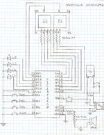
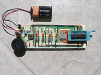
Attached is the schematic and a photo of the hardware.

jerryd
 

Attachments

  • MatchMe0001.jpg
    MatchMe0001.jpg
    2 MB · Views: 121
  • P1010254.JPG
    P1010254.JPG
    783.7 KB · Views: 113

You are assuming all the switches change the logic state from high to low as you close them but there is nothing to set the high state when they are open. Add pull-up resistors to all the switch inputs, I suggest 10K to VDD.

You also don't show any connections to the -MCLR pin, it has to be pulled high for the processor to run.

Brian.
 

betwixt,
Thanks for the reply.
I have a C program that exercises all this hardware and it all works. I am only trying to light one of the leds with the mikroBasic program.

jerryd
 

I stand by my answer. I guess the program itself isn't the problem, it's the configuration bits that are different. if you fix the hardware it will probably work fine. It is always advisable to include the configuration bits in your program, or at least a comment to say what they are. None are shown in your code so most likely they are not configured the same between the C and BASIC versions. In particular look at whether the PORTB pull-ups are enabled and the MCLR is tied high internally.

Brian.
 

betwixt,
I get your point about PORTB and in my C program I use the pullups and all the interrupts work. Here I'm not using the switches or anything else but just portc.1 as a digital I/O output to light one led.

I have compared the C and Basic configurations several times and they look to be the same. MCLR in the C configuration is OFF and it's also OFF in the Basic configuration.

jerryd
 

pjmelect,
Thanks for the reply,

I'm checking portc.1 with my scope and it never goes high.
Here's a list of the scope reading on all the pins:

MCLR, RA0 through RA5 show nothing on the scope
VSS is low
OSC1 shows nothing on the scope
RA6 is low
RC0,RC1,RC2 are at 1.25mv
VUSB,RC4,RC5 show nothing on the scope
RC6 is at 1.25mv
RC7 show nothing on the scope
VSS is low
VDD is at 4.8v
RB0 show nothing on the scope
RB1,RB2 are at 2.1mv
RB3 is low
RB4,RB5,RB6,RB7 show nothing on the scope

jerryd
 

I have to point out that I do not use BASIC but from all those voltages it does look as though the PIC isn't initialized at all and that points to a configuration problem. With the pull-ups enabled it should at least measure a high voltage on the PORTB pins so it isn't even getting that far.

Please try adding a resistor (about 10K) from MCLR to VDD, if the configuration doesn't tie the reset signal high internally it should allow external reset and prove the point. There are of course many other config bits, if one isn't set properly, the chances are the others aren't either.

The other thing you could check is whether the config bits are actually being written to the IC. Make sure whatever you use to program it is reading the config from Mikro and properly writing it to silicon. Perhaps read and compare the config section of the HEX files between C and BASIC to check they really are the same.

Pjmelect's comment is true - there are current limiting resistors on the 7-segment LEDs but you should add them to the individual LEDs as well. It wouldn't stop this problem but you could damage the PIC without them.

Brian.
 

Brian,
All good suggestions.

There are current limiting resistors on the leds, you can see them in the photo. I just forgot to put them on the schematic.

I added a 10K pullup to the MCLR pin, didn't help.

I compared the configuration bits again and as far as I can tell they are the same.

I wrote a C program that is as close to the basic program as I could get it. I even used PORTC = 1 instead of LATCbits.LATC0 = 1 in the C file. It worked.

I tried comparing the C.hex file and the basic.hex file but they are quite different. I don't have a problem reading hex but don't know how to interpret these files.

Here they are:

basic hex file
:100000000EEF00F00000000000EF00F00000000024
:0A0010000000000000000000F3D71C
:10001C00700ED36E070EB46EC26A0F0EC16E946A68
:08002C00010E826EFDD7FFD723
:020000040030CA
:0E0000000C05191EFF0181FF0FC00FE00F401D
:00000001FF

C hex file
:04000000EDEF3FF0F1
:107FDA000001F0EF3FF0700ED36E070EB46E000E84
:107FEA00C26E0F0EC16E000E946E010E826EFAEF13
:067FFA003FF000EF00F073
:020000040020DA
:08000000FFFFFFFFFFFFFFFF00
:020000040030CA
:0E0000000C08191EFF0181FF0FC00FE00F401A
:00000001FF

Looks like everything but the last 3 lines are probably the configuration.
The last 3 lines being the code.

jerryd
 

There is a description of the hex file format here: https://en.wikipedia.org/wiki/Intel_HEX
I will look at your two files later today, I'm busy at the moment. I wouldn't expect them to be the same from two different compilers but the configuration should in theory be identical.
General hex format is:
All content is ASCII hex,
All lines start with a ':'
All bytes are represented by two ASCII characters (example 0x12 would be 31 32)
All lines end with a CRC check byte
The first byte is the line length
The next four bytes are the address the data should be loaded at
The next byte is a record type, normally 00 for data
Up to the CRC is then the data itself.

Brian.
 

Brian,
Maybe these will be easier to read. They are the hex files as shown in the PICKit 2 window.
Meanwhile I'm reading the https://en.wikipedia.org/wiki/Intel_HEX file and will decode as many of these as I can figure out.

Basic HEX
location data
0000 EF0E F000 0000 0000 EF00 F000 0000 0000
0010 0000 0000 0000 0000 D7F3 FFFF 0E70 6ED3
0020 0E07 6EB4 6AC2 0E0F 6EC1 6A94 0E01 6E82
0030 D7FD D7FF FFFF FFFF FFFF FFFF FFFF FFFF

all the remaining are:
FFFF FFFF FFFF FFFF FFFF FFFF FFFF FFFF


C HEX
location data
0000 EFED F03F FFFF FFFF FFFF FFFF FFFF FFFF

all lines between here and the following are:
FFFF FFFF FFFF FFFF FFFF FFFF FFFF FFFF


7FD0 FFFF FFFF FFFF FFFF FFFF 0100 EFF0 F03F
7FE0 0E70 6ED3 0E07 6EB4 0E00 6EC2 0E0F 6EC1
7FF0 0E00 6E94 0E01 6E82 EFFA F03F EF00 F000


There doesn't seem to be much correlation.

jerryd
 

The codes are completely different, however the operation looks similar when the bytes are decoded. There is a difference in the configuration that would be a 'show stopper' though: In the BASIC program the CONFIG1H bits are set to 0x05 which means PIC expects an external clock signal. In the C version it is set to 0x08 which tells it to use its internal oscillator. Without an external clock wired to it, it won't run!

Brian.
 

Brian,
Here's my decode of the basic hex file. I'll do the C hex file next but it will be similar. I really need to figured out which data bits are for configuration.

I don't get why record 5 specifies load address of 0000 since that load address is already used in record 0?

0 :10 0000 00 0EEF00F00000000000EF00F00000000024
1 :0A 0010 00 0000000000000000F3D71C
2 :10 001C 00 700ED36E070EB46EC26A0F0EC16E946A68
3 :08002C00010E826EFDD7FFD723
4 :020000040030CA
5 :0E0000000C05191EFF0181FF0FC00FE00F401D
6 :00000001FF

Record 0 :10 0000 00 0EEF00F00000000000EF00F00000000024
: start of a record
10 16 2 bit data bytes
0000 memory load address
00 record type data
24 = checksum

Record 1 :0A 0016 00 00.00.00.00.00.00.00.00.F3.D7.1C
: start of a record
0A 10 2 bit data bytes
0010 memory load address = 16
00 record type data
1C = checksum

Record 2 :10 001C 00 70.0E.D3.6E.07.0E.B4.6E.C2.6A.0F.0E.C1.6E.94.6A.68
: start of a record
10 16 2 bit data bytes
001C memory load address = 28
00 record type data
68 = checksum

Record 3 :08 002C 00 01.0E.82.6E.FD.D7.FF.D7.23
: start of a record
8 8 2 bit data bytes
002C memory load address = 44
00 record type data
23 = checksum

Record 4 :02 0000 04 0030CA
: start of a record
02 byte count is always 2 with this record type
0000 memory load address ignored
04 record type Extended Linear Address
23 = checksum

Record 5 :0E 0000 00 0C.05.19.1E.FF.01.81.FF.0F.C0.0F.E0.0F.40.1D
: start of a record
0E 14 2 bit data bytes
0000 memory load address = 0?
00 record type data
1D = checksum

Record 6 :00 0000 01FF
: start of a record
00 0 2 bit data bytes
0000 memory load address = 0?
01FF record type EOF

jerryd
--- Updated ---

Brian,
I got it to work

I read that the configuration bits come after record 5 :020000040030CA. That's why the address in record 5 is ignored.

So I copied record 5 from the C hex file and pasted it into the Basic hex file and it worked. Of course this is cheating so now I have to find out why they are different.

I'll keep posting and if you discover anything please post it.

Thanks,
jerryd
 
Last edited:

Brian,
If you get back on this forum I would like to thank you for steering me in the right direction.

I learned all about the .hex files, maybe more than I needed to know, and that's where my problem was. It was just the "Oscillator selection" configuration bit. There are several choices for "Internal oscillator" that all are similar so it was difficult to compare the one used in my C file with the default one in basic. I tried each one until the record in the hex file was right.

jerryd
 

Speaking with more than half a century in the electronics business, I would always advise you to embed the configuration in the source code. I'm not a fan of Mikroe programs and I don't use Windows so I'm not that familiar with the syntax they use but I would advise you to read the Microchip documents on their XC8 compiler to see how you can include all the settings in the source.

As an alternative to MikroBasic, I would suggest looking at Oshonsoft's simulator IDE programs. I have no affiliation with Oshonsoft but they do seem to produce compact code and it is well documented if a little quirky in the screen presentation. They can also reverse engineer HEX files to assembler, including the configuration bits!

Brian.
 

Status
Not open for further replies.

Similar threads

Part and Inventory Search

Welcome to EDABoard.com

Sponsor

Back
Top