Continue to Site

Welcome to EDAboard.com

Welcome to our site! EDAboard.com is an international Electronics Discussion Forum focused on EDA software, circuits, schematics, books, theory, papers, asic, pld, 8051, DSP, Network, RF, Analog Design, PCB, Service Manuals... and a whole lot more! To participate you need to register. Registration is free. Click here to register now.

[PIC] PIC16F887 > ADC > External Vref of 2.5 V

Eric_O

Advanced Member level 4
Full Member level 1
Joined
May 31, 2020
Messages
105
Helped
0
Reputation
0
Reaction score
0
Trophy points
16
Activity points
1,005
I decided to use an external voltage reference of 2.5 V on AN3 with LM385-Z-2.5.

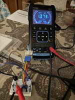
Regarding the Texas Instrument datasheet of LM385-ADJ, and schematics / formula at page 2, figure 6, when using 5 V for VCC, R2 = R3 = 10 K, and when testing the output voltage at pin « + » of the regulator, without being connected to AN3 of PIC, I never obtain around 2.5 V. I only obtain 1.373 V.

Some one can enlighten me ?

Thanks 🙏🏻
 

Attachments

  • LM385 ADJ.pdf
    1.5 MB · Views: 11
  • IMG_7269.jpeg
    IMG_7269.jpeg
    1.8 MB · Views: 9
Hi,

it´s not clear how you wired it --> show a schematic. Hand drawn will do. But it should be complete with informations of power supply and ho/where you connected the DVM (both wires)

You said you use the
LM385-Z-2.5.
This already is a FIXED 2.5V voltage reference that does not need resistors to adjust the output voltage. It is preset to output 2.5V!

But you linked a datasheet to LM385-ADJ ... which is the ADJustable version of voltage references. With them you need resistors .. and to adjust the output voltage in a wide range.

--> use the correct datasheet!

Klaus
 

LaTeX Commands Quick-Menu:

Similar threads

Part and Inventory Search

Welcome to EDABoard.com

Sponsor

Back
Top