Continue to Site

Welcome to EDAboard.com

Welcome to our site! EDAboard.com is an international Electronics Discussion Forum focused on EDA software, circuits, schematics, books, theory, papers, asic, pld, 8051, DSP, Network, RF, Analog Design, PCB, Service Manuals... and a whole lot more! To participate you need to register. Registration is free. Click here to register now.

PIC16F877A LED Array Tachometer (In progress)

Status
Not open for further replies.

shsn

Junior Member level 3
Joined
Nov 28, 2012
Messages
26
Helped
0
Reputation
0
Reaction score
0
Trophy points
1,281
Activity points
1,523
Hi,

This is my first time actually getting into microcontrollers and designing my own PCB board, having so much fun :)
What I'm working on is to measure engine's rotational speed using an array of LEDs, which is essentially 'shift light'.
Once completed this will actually be installed in an open wheel race car that we built in an university society.
Although the project is not yet finished and having a few problems with the PIC but it's getting there.
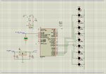
schematic.png

Schematics. Recieving analogue voltage from Motec ECU to PIC's ADC.
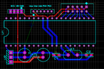
pcblayout.png

Draft version of PCB layout.

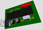
pcbmodel.png

3D model of PCB.

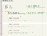
coding.png

An extract of coding.

Component value choice may not be the optimal value as I'm just getting into the world of MCUs and I don't think the coding is very efficient. Honestly I don't exactly know what I'm doing :lol:

Cheers.

Eric.
 

can u post the full code and can please elaborate actually what are you doing......
 

I have an ECU already installed in the car managing cooling systems and other components. It is programmable to output a certain voltage ranging from 0 to 5V depending on the engine's rotational speed. So the output signal from ECU will be fed to analogue port of the PIC (in my case AN1) to measure the voltage. Then with bit of coding (ADC conversion) I want to turn LED(s) on incrementally depending on the voltage received by the PIC. For instance; when 0.5V is received, the first LED will be on; when 3.0V is received, the first 4 LEDs will be on and so on.

Here is my code.

Code:
unsigned int adc_val;
unsigned long volts_m;

void main() {

     TRISD   = 0;                               // PORTD all output to LED
     TRISC   = 0;                               // PORTC all output to LED
     ADCON1  = 0x88;                            // configure Vref, and analog channels
     TRISA   = 0xFF;                            // designate PORTA as input
     
     for (;;) {
           adc_val = ADC_read(1);               // get ADC value for U from channel 1
           volts_m = (long)adc_val*5000/1023;   // Convert ADC value to millivolts
           
           // 0 LED, Target voltage = 0.0v, Range 0.0 - 0.35v
           if (volts_m >= 0 && volts_m <= 350) {
              PORTD = 0b00000000;
              PORTC = 0b00000000;
           }
           // 1 LED, Target voltage = 0.5v, Range 0.35 - 0.7v
           if (volts_m > 350 && volts_m <= 700) {
              PORTD = 0b00000100;
              PORTC = 0b00000000;
           }
           // 2 LEDs, Target voltage = 1.0v, Range 0.7 - 1.3v
           if (volts_m > 700 && volts_m <= 1300) {
              PORTD = 0b00001100;
              PORTC = 0b00000000;
           }
           // 3 LEDs, Target voltage = 1.5v, Range 1.3 - 1.7v
           if (volts_m > 1300 && volts_m <= 1700) {
              PORTD = 0b00001100;
              PORTC = 0b00010000;
           }
           // 4 LEDs, Target voltage = 2.0, Range 1.7 - 2.3v
           if (volts_m > 1700 && volts_m <= 2300) {
              PORTD = 0b00001100;
              PORTC = 0b00110000;
           }
           // 5 LEDs, Target voltage = 2.5, Range 2.3 - 2.7v
           if (volts_m > 2300 && volts_m <= 2700) {
              PORTD = 0b00001100;
              PORTC = 0b01110000;
           }
           // 6 LEDs, Target voltage = 3.0, Range 2.7 - 3.3v
           if (volts_m > 2700 && volts_m <= 3300) {
              PORTD = 0b00001100;
              PORTC = 0b11110000;
           }
           // 7 LEDs, Target voltage = 3.5, Range 3.3 - 3.7v
           if (volts_m > 3300 && volts_m <= 3700) {
              PORTD = 0b00011100;
              PORTC = 0b11110000;
           }
           // 8 LEDs, Target voltage = 4.0, Range 3.7 - 4.3v
           if (volts_m > 3700 && volts_m <= 4300) {
              PORTD = 0b00111100;
              PORTC = 0b11110000;
           }
           // 9 LEDs, Target voltage = 4.5, Range 4.3 - 4.7v
           if (volts_m > 4300 && volts_m <= 4700) {
              PORTD = 0b01111100;
              PORTC = 0b11110000;
           }
           // Flash LEDs, Target voltage = 5.0, Range 4.7 - 5.0v
           if (volts_m > 4700 && volts_m <= 5000) {
              do {
                 PORTD = 0b00000000;
                 PORTC = 0b00000000;
                 delay_ms(300);
                 PORTD = 0b01111100;
                 PORTC = 0b11110000;
                 delay_ms(300);

              }
              while (volts_m > 4700 && volts_m <= 5000);
           }
     }
}

I welcome any suggestions to code it more efficiently or better way of achieving the same task.
 

the code looks fine,

if u wants make it efficient then use if and else if in next if conditions, this avoids the checking of the next if conditions,

if u want, u can also use switch condition,

hope this helps u
 

Status
Not open for further replies.

Part and Inventory Search

Welcome to EDABoard.com

Sponsor

Back
Top