Continue to Site

Welcome to EDAboard.com

Welcome to our site! EDAboard.com is an international Electronics Discussion Forum focused on EDA software, circuits, schematics, books, theory, papers, asic, pld, 8051, DSP, Network, RF, Analog Design, PCB, Service Manuals... and a whole lot more! To participate you need to register. Registration is free. Click here to register now.

PIC16f1527 UART1 Declaration problem

Status
Not open for further replies.

ragav4456

Full Member level 4
Full Member level 4
Joined
Aug 1, 2012
Messages
228
Helped
19
Reputation
38
Reaction score
17
Trophy points
1,308
Activity points
2,568
Hello sir
I Have doubt in PIC16f1527 IC UART1.

How to select UART1 and how to configure uart1 bits?
 

MPLAB Hitech C compiler :)
 

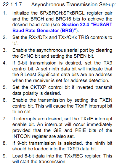
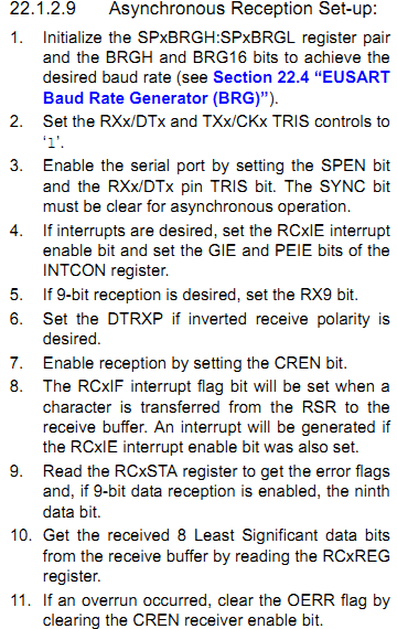
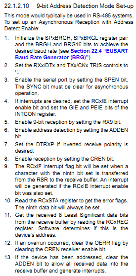
Here are the steps (from the datasheet: https://ww1.microchip.com/downloads/en/DeviceDoc/41458B.pdf):

9109842200_1359607767.png


9535312300_1359607810.png


4909914300_1359607853.png


Hope this helps.
Tahmid.
 

For UART1 registers are

SP1BRGL
SP1BRGH
TX1REG
TX1STA
RC1STA


For UART2 registers are

SP2BRGL
SP2BRGH
TX2REG
TX2STA
RC2STA

For 9800 Baud 8 bit transmission No parity, 1 stop bits

TX1STA
CSRC = 0 or 1 Asyncronous Mode
TX9 = 0 8 bit Tx
TXEN = 1 Transmit is enabled
SYNC = 0 Asynchronous mode
SENDB = 1
BRGH = 0 for low speed
1 for hign speed
TRMT = 1 empty
TX9D = 0 or 1 Async mode

RC1STA
SPEN = 1
RX9 = 0
SREN = 0 or 1 Ascyn mode
CREN = 1 enable receiver
ADDEN = 0
FERR = 0
OERR = 0
RX9D = 0 or 1 Async mode
 

Thanks,
I am using Hi-tech c compiler. Embedded c

TX1STAbits.SYNC = 0; // Correct or Not..?
 

Ya Iam using Asynchronous mode. Configure format?


what is the difference between 16f877 IC and 16f1527 IC UART function?
 

I don't know the difference as I haven't seen the datasheet. I think the only difference is the later has 2 UART. Usually the working of UART will be the same.
What configure format do you want?
 

how to declare UART1 selection bits? // How to declare SPEN bit?

SPEN=1; // error;
 

SPENUART.PNG

Check the datasheet. SPEN bit is available.
 

how to declare UART1 selection bits? // How to declare SPEN bit?

SPEN=1; // error;

There are 2 SPEN bits in 16F1527 - one for UART1 and another for UART2.

Can you upload the header file for 16F1527?

Without looking at the header file, I can't say what you need to write, at least not with certainty.

You may try:
Code:
SPEN1 = 1;
or
Code:
SP1EN = 1;

Hope this helps.
Tahmid.
 

SP1EN = 1; is undefined identifier.

pic16f1527.h

#ifndef _HTC_H_
#warning Header file pic16f1527.h included directly. Use #include <htc.h> instead.
#endif

/* header file for the MICROCHIP PIC microcontroller
* 16F1527
*/


#ifndef __PIC16F1527_H
#define __PIC16F1527_H

//
// Configuration mask definitions
//


// Config Register: CONFIG1
#define CONFIG1 0x8007
// Oscillator Selection
// ECH, External Clock, High Power Mode (4-20 MHz): device clock supplied to CLKIN pin
#define FOSC_ECH 0xFFFF
// ECM, External Clock, Medium Power Mode (0.5-4 MHz): device clock supplied to CLKIN pin
#define FOSC_ECM 0xFFFE
// ECL, External Clock, Low Power Mode (0-0.5 MHz): device clock supplied to CLKIN pin
#define FOSC_ECL 0xFFFD
// INTOSC oscillator: I/O function on CLKIN pin
#define FOSC_INTOSC 0xFFFC
// EXTRC oscillator: External RC circuit connected to CLKIN pin
#define FOSC_EXTRC 0xFFFB
// HS Oscillator, High-speed crystal/resonator connected between OSC1 and OSC2 pins
#define FOSC_HS 0xFFFA
// XT Oscillator, Crystal/resonator connected between OSC1 and OSC2 pins
#define FOSC_XT 0xFFF9
// LP Oscillator, Low-power crystal connected between OSC1 and OSC2 pins
#define FOSC_LP 0xFFF8
// Watchdog Timer Enable
// WDT enabled
#define WDTE_ON 0xFFFF
// WDT enabled while running and disabled in Sleep
#define WDTE_NSLEEP 0xFFF7
// WDT controlled by the SWDTEN bit in the WDTCON register
#define WDTE_SWDTEN 0xFFEF
// WDT disabled
#define WDTE_OFF 0xFFE7
// Power-up Timer Enable
// PWRT disabled
#define PWRTE_OFF 0xFFFF
// PWRT enabled
#define PWRTE_ON 0xFFDF
// MCLR Pin Function Select
// MCLR/VPP pin function is MCLR
#define MCLRE_ON 0xFFFF
// MCLR/VPP pin function is digital input
#define MCLRE_OFF 0xFFBF
// Flash Program Memory Code Protection
// Program memory code protection is disabled
#define CP_OFF 0xFFFF
// Program memory code protection is enabled
#define CP_ON 0xFF7F
// Brown-out Reset Enable
// Brown-out Reset enabled
#define BOREN_ON 0xFFFF
// Brown-out Reset enabled while running and disabled in Sleep
#define BOREN_NSLEEP 0xFDFF
// Brown-out Reset controlled by the SBOREN bit in the BORCON register
#define BOREN_SBODEN 0xFBFF
// Brown-out Reset disabled
#define BOREN_OFF 0xF9FF
// Clock Out Enable
// CLKOUT function is disabled. I/O or oscillator function on the CLKOUT pin
#define CLKOUTEN_OFF 0xFFFF
// CLKOUT function is enabled on the CLKOUT pin
#define CLKOUTEN_ON 0xF7FF
// Internal/External Switchover
// Internal/External Switchover mode is enabled
#define IESO_ON 0xFFFF
// Internal/External Switchover mode is disabled
#define IESO_OFF 0xEFFF
// Fail-Safe Clock Monitor Enable
// Fail-Safe Clock Monitor is enabled
#define FCMEN_ON 0xFFFF
// Fail-Safe Clock Monitor is disabled
#define FCMEN_OFF 0xDFFF


// Config Register: CONFIG2
#define CONFIG2 0x8008
// Flash Memory Self-Write Protection
// Write protection off
#define WRT_OFF 0xFFFF
// 000h to 1FFh write protected, 200h to 3FFFh may be modified by PMCON control
#define WRT_BOOT 0xFFFE
// 000h to FFFh write protected, 2000h to 3FFFh may be modified by PMCON control
#define WRT_HALF 0xFFFD
// 000h to 3FFFh write protected, no addresses may be modified by PMCON control
#define WRT_ALL 0xFFFC
// Voltage Regulator Capacitor Enable bit
// VCAP pin function disabled
#define VCAPEN_OFF 0xFFFF
// VCAP pin function enabled
#define VCAPEN_ON 0xFFEF
// Stack Overflow/Underflow Reset Enable
// Stack Overflow or Underflow will cause a Reset
#define STVREN_ON 0xFFFF
// Stack Overflow or Underflow will not cause a Reset
#define STVREN_OFF 0xFDFF
// Brown-out Reset Voltage Selection
// Brown-out Reset Voltage (VBOR) set to 2.4V
#define BORV_LO 0xFFFF
// Brown-out Reset Voltage (VBOR) set to 2.7V
#define BORV_HI 0xFBFF
// Low-Power Brown Out Reset
// Low-Power BOR is disabled
#define LPBOR_OFF 0xFFFF
// Low-Power BOR is enabled
#define LPBOR_ON 0xF7FF
// Low-Voltage Programming Enable
// Low-voltage programming enabled
#define LVP_ON 0xFFFF
// High-voltage on MCLR/VPP must be used for programming
#define LVP_OFF 0xDFFF


//
// Special function register definitions
//


// Register: INDF0
volatile unsigned char INDF0 @ 0x000;
// bit and bitfield definitions

...
...
...
 

Can you post the complete .h file?

The portion you showed does not contain the UART definitions section.
 

I solved UART communication.

I received data from microcontroller but datas are interchanged. Microcontroller sends different datas.

what is the problem?
 

this is my uart code.kindly check the code

Code:
#include <htc.h>
#include "sci.h"

unsigned int uiRS232Error = 0;

unsigned char sci_Init(unsigned long int baud, unsigned char ninebits)
{
	int X;
	unsigned long tmp;
	uiRS232Error = 0;

	tmp = 16UL * baud;
	X = (int)(FOSC/tmp) - 1;
	if((X>255) || (X<0))
	{
		tmp = 64UL * baud;
		X = (int)(FOSC/tmp) - 1;
		if((X>255) || (X<0))
		{
			return 1;	
		}
		else

			TX1STAbits.BRGH = 0;	/* low baud rate */
	}
	else
	TX1STAbits.BRGH = 1;	/* high baud rate */
	SPBRG = X;	/* set the baud rate */
        BAUD1CONbits.BRG16=1;
	BAUD1CONbits.ABDOVF=0;
	BAUD1CONbits.RCIDL=0;
	BAUD1CONbits.SCKP=0;
	BAUD1CONbits.WUE=0;
	BAUD1CONbits.ABDEN=1;
	TX1STAbits.SYNC = 0;           /* asynchronous */
	TX1STAbits.SENDB = 0;

	RC1STAbits.SPEN = 1;	/* enable serial port pins */
	RC1STAbits.CREN = 1;	/* enable reception */
	RC1STAbits.SREN = 0;	/* no effect */
	PIE1bits.TX1IE = 1;	/* disable tx interrupts */
	PIE1bits.RC1IE = 1;	/* disable rx interrupts */
	TX1STAbits.TX9  = ninebits?1:0;	/* 8- or 9-bit transmission */
	RC1STAbits.RX9  = ninebits?1:0;	/* 8- or 9-bit reception */
	RC2STAbits.ADDEN=0;
	TX1STAbits.TXEN = 1;	/* enable the transmitter */
	PIR1bits.TX1IF = 0;	/* enable tx interrupts */
	PIR1bits.RC1IF = 0; /* enable rx flag */

	return 0;
}

void sci_PutByte(unsigned char byte)
{	unsigned long ulICnt=0;
	
	uiRS232Error = 0;

	while(!PIR1bits.TX1IF && ulICnt < WAIT_TICK_MAX)	
	{	ulICnt++;
	}
	TX1REG = byte;

	if(ulICnt >= WAIT_TICK_MAX)
	{	uiRS232Error = 1;
	}
	return;
}

unsigned char sci_GetByte(void)
{	unsigned long ulICnt=0;

	uiRS232Error = 0;

	while(!PIR1bits.RC1IF && ulICnt < WAIT_TICK_MAX)	
	{	ulICnt++;
	}

	sci_CheckOERR();

	if(ulICnt >= WAIT_TICK_MAX)
	{	uiRS232Error = 1;
	}

	return RC1REG;	/* RXD9 and FERR are gone now */
}

unsigned char sci_CheckOERR(void)
{
	if(RC1STAbits.OERR)	
	{
		RC1STAbits.CREN = 0;
		RC1STAbits.CREN = 1;
		return 1;
	}
	
	return 0;
 }

#define sci_PutNinth(bitnine)	(TX9D = bitnine?1:0;)

unsigned char sci_GetNinth(void)
{
	while(!PIR1bits.RC1IF)
		continue;
	
	return RC1STAbits.RX9D;	
}

unsigned char sci_GetFERR(void)
{
	while(!PIR1bits.RC1IF)
		continue;
	
	return RC1STAbits.FERR;
}
 
What is the purpose of the 2 nested if statements?

Code C - [expand]
1
2
3
4
5
6
7
8
9
10
11
12
13
14
15
16
tmp = 16UL * baud;
    X = (int)(FOSC/tmp) - 1;
    if((X>255) || (X<0))
    {
        tmp = 64UL * baud;
        X = (int)(FOSC/tmp) - 1;
        if((X>255) || (X<0))
        {
            return 1;   
        }
        else
 
            TX1STAbits.BRGH = 0;    /* low baud rate */
    }
    else
    TX1STAbits.BRGH = 1;    /* high baud rate */


Status
Not open for further replies.

Similar threads

Part and Inventory Search

Welcome to EDABoard.com

Sponsor

Back
Top