sr2w
Junior Member level 1

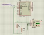
1) I am trying to read the ambient temperature register in MCP9801 with the following code. My simulation is getting stuck on one line (highlighted in code below). I have attached the Simulation log.JPG.
2) I have referred to the the relevant discussions previously done, but still
wasn't able to figure the problem in my code.
https://www.microchip.com/forums/m956027.aspx
https://www.microchip.com/forums/m852246.aspx
3) It's been two weeks I have started with MPLAB and PIC controllers. I have written Blinky LED for PIC16F1508, 688 and 1887. Also I have done UART communication using PIC16F1887.
Code:
#include <xc.h>
#include <stdio.h>
#include <stdlib.h>
#include"pic16f1508.h"

#define _XTAL_FREQ 16000000

void initialise()
{
INTCONbits.GIE = 0; // GLOBAL INTERRUPTS DISABLED
INTCONbits.PEIE = 0; // PERIPHERAL INTERRUPTS DISABLED
PIE3 = 0; // INTERRUPTs DISABLED

SSP1STATbits.SMP = 1; // Slew rate control disabled for Standard Speed mode (100 kHz and 1 MHz)
SSP1STATbits.CKE = 0; // Disable SMBus specific inputs
SSP1ADD = 0x03; // CLOCK OF 31.25 KHZ SET
SSP1MSK = 0; // NO MASK
TRISBbits.TRISB4 = 1; //
TRISBbits.TRISB6 = 1;
ANSELB = 0;

PIE1bits.SSP1IE = 0;
SSP1CON1bits.WCOL = 0; // 1 - I2C CAN'T BE STARTED, 0 - GOOD TO GO
SSP1CON1bits.SSPOV = 0;// 1 - BYTE RECEIVED WHEN SSP1BUF STILL HOLDING LAST BYTE
                                       // 0 - GOOD TO GO
SSP1CON1bits.SSPEN = 1; // ENABLE I2C
SSP1CON1bits.CKP = 0;
SSP1CON1bits.SSPM0 = 0;
SSP1CON1bits.SSPM1 = 0;
SSP1CON1bits.SSPM2 = 0;
SSP1CON1bits.SSPM3 = 1; // SSPM - 1000, MASTER MODE SELECTED

SSP1CON2 = 0x00;
SSP1BUF = 0;
TRISC = 1;
}

void first_write()
{
SSP1CON2bits.SEN = 1; // START I2C

while(SSP1CON2bits.SEN | SSP1STATbits.R_nW); // WAIT -(I GET STUCK OVER HERE!!!)

SSP1BUF = 0x90; // 1001 - DEFAULT ADDRESS(MCP9801), 000 - I HAVE SET THE
                           // LAST THREE BITS OF ADDRESS (MCP9801), 0 - WRITE

while(SSP1CON2bits.ACKSTAT); // SEE IF ACKNOWLEDGEMENT HAS BEEN RECEIVED//
SSP1BUF = 0; // TO SET THE REGISTER POINTER TO 00 FOR TEMPERATURE

SSP1CON2bits.PEN = 1; // STOP I2C
}
void one_read()
{
SSP1CON2bits.SEN = 1;
SSP1BUF = 0x91; // 1001 - DEFAULT ADDRESS, 000 - I HAVE SET THE LAST THREE

                           //  BITS OF ADDRESS (MCP9801), 1 - READ

while(0 == SSP1STATbits.BF); // WAIT WHILE RECEPTION NOT COMPLETE
SSP1CON2bits.ACKDT = 0; // SEND ACKNOWLEDGEMENT
SSP1CON2bits.PEN = 1; // STOP I2C
PORTC = SSP1BUF; //

}
void main(void)
{
        {
             initialise();
             first_write();
             one_read();
        }
}

