TheMartian
Junior Member level 3

From what I understand, the Extended SPI is like SPI but with extra data line.
I wonder how do I support it on PIC and mikroC?
There is a "simple" SPI library for that:
https://download.mikroe.com/documents/compilers/mikroc/pic/help/spi_library.htm
Do I have to somehow extend the hardware SPI of PIC18F, or create software SPI using any selected digital pins and write whole SPI system from scratch in my code?
I am looking at the datasheet.
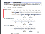
The signals for READ ID command:

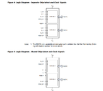
The pinout of chip:

For me, it looks like I can do "READ ID" in "Extended" mode just by using 4 signals: Clock (C_1), DQ0, DQ1 and S (obviously). I don't get where is the extra line needed.
My question is: where is mistake in my understanding. Can I do "READ ID" command from screenshots with simple MikroC SPI library?
PS: I attach the source datasheet of screenshots.
View attachment MICT-S-A0002963421-1.pdf
Micron extended SPI protocol is the standard SPI protocol with additional commands
that extend functionality and enable address or data transmission on multiple DQn
lines.
To initiate a command, S# is driven LOW. For extended SPI protocol, input is on DQ0/
DQ4, output on DQ1/DQ5.
I wonder how do I support it on PIC and mikroC?
There is a "simple" SPI library for that:
https://download.mikroe.com/documents/compilers/mikroc/pic/help/spi_library.htm
Do I have to somehow extend the hardware SPI of PIC18F, or create software SPI using any selected digital pins and write whole SPI system from scratch in my code?
I am looking at the datasheet.
The signals for READ ID command:

The pinout of chip:

For me, it looks like I can do "READ ID" in "Extended" mode just by using 4 signals: Clock (C_1), DQ0, DQ1 and S (obviously). I don't get where is the extra line needed.
My question is: where is mistake in my understanding. Can I do "READ ID" command from screenshots with simple MikroC SPI library?
PS: I attach the source datasheet of screenshots.
View attachment MICT-S-A0002963421-1.pdf
