vikash23
Full Member level 2

Hi,
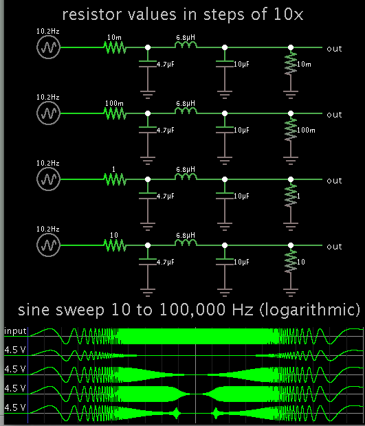
Could any one please tell me what would be the cut off frequency for the below PI filter.
These are two different filters and please explain me how to calculate the values.
https://obrazki.elektroda.pl/4223844500_1409307162.jpg
Could any one please tell me what would be the cut off frequency for the below PI filter.
These are two different filters and please explain me how to calculate the values.
https://obrazki.elektroda.pl/4223844500_1409307162.jpg