Vermes
Advanced Member level 4

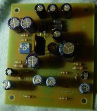
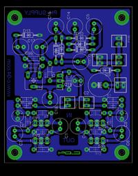
It is a 48V power supply, so called PHANTOM for studio microphones. Schematic shows that presented here construction is the simplest power multiplier with an attached adjustable output voltage on the transistor TIP121 (in the schematic – BD139). The transistor has to withstand voltage over 80V and has relatively low resistance between the connectors. High resistance will reduce the performance and cause the transistor heating up. Transistor TIP121 should be inserted on the board inversely, i.e. in relation to the BD139. It is important that the connected power supply must produce an alternating voltage (it can not be constant nor stabilized). It can be 12V or 15V. After assembly, set the output voltage by potentiometer PH 10k (simultaneously for both outputs). You can connect two microphones, that you want to supply and independently switch off voltage for them. The switches can be plugged into PH1 and PH2.
PWR, PWRCO and SW connectors are for:
- PWR – for connecting the power supply
- PWRCO – for connecting another converter in order to supply 4 microphones using a single power supply
- SW – switch of the device
Connectors SV1, SV2, SV3, SV4 are for:
- SV1 (microphone 1) and SV2 (microphone 2) – for connecting the microphones
- SV3 (microphone 1) and SV4 (microphone 2) – for connecting mixer outputs etc.
LED connector is used for connecting control lights of both global supply on and individual micriphones supply on. Dimensions of the board are: 67x55mm.
Output voltage was set to approximately 49-51V, after conneting a microphone, it drops anyway.
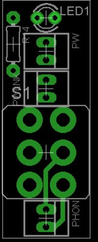
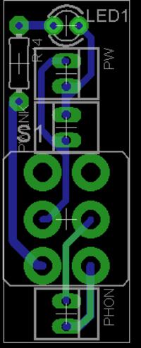
Small boards dimensions are: 34x13mm. PW connector can be connected to the LED connector on the converter board. Pwlnk should be conencted to another small board to PW connector and in each further board in the same way. PHON connector of individual small boards goes to PH1 and PH2 on the converter board. A small board can also be used as power supply, but then you have to connect PHON to SW. Each turn on the switches is then indicated by lighting LED above (or under – depends on how the small board is placed) the switch.
NOTE! On the scheme descriptions of the LEDs are incorrect – instead 4148 there should be 4007.
Pictures:
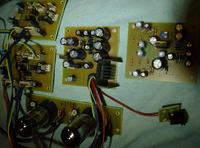
The same converter was used to power the microphones as Phantom and lamps (anode voltage).
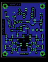

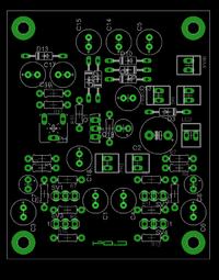

Link to original thread (useful attachment) – Zasilacz PHANTOM do mikrofonów studyjnych.