dammert89
Newbie level 2

Good day
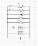
I am busy with a circuit that I would like to build for a wine cooler/pourer. I have built the enclosure for the bottles and hardware. I just need to do the electronics part (Not my strongest ability). Below you will find a schematic. Please give me your opinions after looking at the specific parts in the diagram.
Only one of the motors (From M1 and M2) can be used at a time. Here is the parts list:
Parts
M1 and M2: **broken link removed**
S1 and S2: switches (Possibly arcade machine style buttons if they can handle the load)
L1: **broken link removed**
M3 and M4: Basic PC 12V fans (4.5-13.8VDC, 165mA, 2W, 3KRPM, 51CFM)
TEC1: Peltier cooler 6A
THER1: Thermometer LCD
(This is all the information on the thermometer I have)
R1: Potentiometer (Need advice on this one)

Power supply will be an AC to DC PSU like this. (Not sure yet on the amperage yet)
My main electronics supplier is Mantech as I am from South Africa.
What improvements/suggestions can you advise? I don't want to make it too complicated though. Haven't ordered any of the parts other than those for the enclosure. Another problem I might have is if the 1 peltier doesn't work and I have to replace it with a bigger one or 2 of the same.
Thanks
I am busy with a circuit that I would like to build for a wine cooler/pourer. I have built the enclosure for the bottles and hardware. I just need to do the electronics part (Not my strongest ability). Below you will find a schematic. Please give me your opinions after looking at the specific parts in the diagram.
Only one of the motors (From M1 and M2) can be used at a time. Here is the parts list:
Parts
M1 and M2: **broken link removed**
S1 and S2: switches (Possibly arcade machine style buttons if they can handle the load)
L1: **broken link removed**
M3 and M4: Basic PC 12V fans (4.5-13.8VDC, 165mA, 2W, 3KRPM, 51CFM)
TEC1: Peltier cooler 6A
THER1: Thermometer LCD
(This is all the information on the thermometer I have)
R1: Potentiometer (Need advice on this one)

Power supply will be an AC to DC PSU like this. (Not sure yet on the amperage yet)
My main electronics supplier is Mantech as I am from South Africa.
What improvements/suggestions can you advise? I don't want to make it too complicated though. Haven't ordered any of the parts other than those for the enclosure. Another problem I might have is if the 1 peltier doesn't work and I have to replace it with a bigger one or 2 of the same.
Thanks
Last edited:

