David Gordon
Newbie level 2

Hi,
I apologise in advance if I am asking silly questions, or what I'm asking is fairly obvious, but this is the first time I've done something like this and despite a bit of reading am a little shakey on what is required.
I am in the process of building a custom rackmount case for a couple of Raspberry Pis and as part of this am looking at how best to facilitate any swaps outs or internal changes that may be required in future. It occured to me that a custom PCB that essentially allows the external connections to passthrough to internal connections would be the easiest way to facilitate a quick swap out/upgrade if required.
I've attached a basic sketch up of the case internals
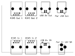
Essentially, what I require is a PCB with two RJ45 ports, 2 x USB ports and a power port externally - with these ports replicated internally with everything just passed through.
Mock up
I'm under the impression that running running traces between the internal and external RJ45 connectors should facilitate passthrough, and the same with the USB connectors. However, I'm not sure how best to handle the power passthrough, can it be passed through with traces, or does it need conditioning? For reference the power will be then sent straight to a high quality USB hub (and then through some pre-built PCB switch gear and then to the Pis.)
Any advice or guidance would be appreciated.
I apologise in advance if I am asking silly questions, or what I'm asking is fairly obvious, but this is the first time I've done something like this and despite a bit of reading am a little shakey on what is required.
I am in the process of building a custom rackmount case for a couple of Raspberry Pis and as part of this am looking at how best to facilitate any swaps outs or internal changes that may be required in future. It occured to me that a custom PCB that essentially allows the external connections to passthrough to internal connections would be the easiest way to facilitate a quick swap out/upgrade if required.
I've attached a basic sketch up of the case internals

Essentially, what I require is a PCB with two RJ45 ports, 2 x USB ports and a power port externally - with these ports replicated internally with everything just passed through.
Mock up

I'm under the impression that running running traces between the internal and external RJ45 connectors should facilitate passthrough, and the same with the USB connectors. However, I'm not sure how best to handle the power passthrough, can it be passed through with traces, or does it need conditioning? For reference the power will be then sent straight to a high quality USB hub (and then through some pre-built PCB switch gear and then to the Pis.)
Any advice or guidance would be appreciated.

