Passive High Pass Filter Through a Differential Input
- Thread starter Iuri
- Start date
- Status
- Not open for further replies.


goldsmith
Advanced Member level 6

- Joined
- Dec 14, 2010
- Messages
- 3,981
- Helped
- 741
- Reputation
- 1,486
- Reaction score
- 726
- Trophy points
- 1,413
- Location
- Tehran - IRAN
- Activity points
- 24,546
Hi Iuri
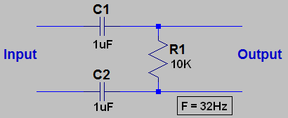
Where is R2 in your picture ? it is a usual term to use C1=C2=C/2 in calculations .
Best Wishes
Goldsmith
Where is R2 in your picture ? it is a usual term to use C1=C2=C/2 in calculations .
Best Wishes
Goldsmith


D.A.(Tony)Stewart
Advanced Member level 7

- Joined
- Sep 26, 2007
- Messages
- 10,294
- Helped
- 1,867
- Reputation
- 3,739
- Reaction score
- 2,515
- Trophy points
- 1,413
- Location
- Richmond Hill, ON, Canada
- Activity points
- 64,857
For best sensitivity , low offset and best common mode noise rejection use an Instrumentation Amp IC ( 3 opamps) and use the series RC to define your HPF cutoff (fc=1/(2pi RC) instead of R7 You can get these in 1 chip too. R6=R5 and gain = R5/R7 for 1st stage... R2/R1 for 2nd stage
goldsmith
Advanced Member level 6
- Joined
- Dec 14, 2010
- Messages
- 3,981
- Helped
- 741
- Reputation
- 1,486
- Reaction score
- 726
- Trophy points
- 1,413
- Location
- Tehran - IRAN
- Activity points
- 24,546
Hi Godfreyl
What you said ? are you sure about that ? if yes see below , please :
Consider that you have two capacitors in series together , the equal capacitor will be c/2 if both are correspond together . thus : if C1=C2=C/2 .
Respect
Goldsmith
What you said ? are you sure about that ? if yes see below , please :
Consider that you have two capacitors in series together , the equal capacitor will be c/2 if both are correspond together . thus : if C1=C2=C/2 .
Respect
Goldsmith
- Joined
- Jan 22, 2008
- Messages
- 53,701
- Helped
- 14,811
- Reputation
- 29,919
- Reaction score
- 14,439
- Trophy points
- 1,393
- Location
- Bochum, Germany
- Activity points
- 303,603
Yes, you calculated the time constant for given C values, while godfreyl calculated capacitor values to achieve a given cut off frequency. Both calculations are correct.
LvW
Advanced Member level 6
So, should I use C1=C2=C*2 to achieve my cutoff frequency?
Iuri, I don't know what you are going to connect at the diff. high pass output - however, realize that there is no ground connection (no bias current for a possible next stage).
D.A.(Tony)Stewart
Advanced Member level 7
- Joined
- Sep 26, 2007
- Messages
- 10,294
- Helped
- 1,867
- Reputation
- 3,739
- Reaction score
- 2,515
- Trophy points
- 1,413
- Location
- Richmond Hill, ON, Canada
- Activity points
- 64,857
Do you need a steep Nyquist filter? 1st order LPF may not be adequate.
Can you define spectrum?
Can you define spectrum?
D.A.(Tony)Stewart
Advanced Member level 7
- Joined
- Sep 26, 2007
- Messages
- 10,294
- Helped
- 1,867
- Reputation
- 3,739
- Reaction score
- 2,515
- Trophy points
- 1,413
- Location
- Richmond Hill, ON, Canada
- Activity points
- 64,857
It depends on the signal content above 500Hz . It will appear as noise with frequency transformed. (Alias)
Anything at 1KHz and all harmonics will appear as DC.
Anything at 1KHz and all harmonics will appear as DC.
Iuri
Member level 2
I know about Nyquist Theorem, but this is the first time I design something like that, so I don't have experience at all in anti-aliasing filter.
Should I use a higher order passive LPF or a active one?
Thank you.
Should I use a higher order passive LPF or a active one?
Thank you.
- Status
- Not open for further replies.
Similar threads
-
-
ADS How to choose BJT for passive mixer from Vendors libraries?
- Started by Quazzy
- Replies: 0
-
-
Selection for sampling frequency at low and high frequency input signal of SD ADC?
- Started by Henry98
- Replies: 5
-