Continue to Site

Welcome to EDAboard.com

Welcome to our site! EDAboard.com is an international Electronics Discussion Forum focused on EDA software, circuits, schematics, books, theory, papers, asic, pld, 8051, DSP, Network, RF, Analog Design, PCB, Service Manuals... and a whole lot more! To participate you need to register. Registration is free. Click here to register now.

[SOLVED] Parallel > Serial > Parallel conversion

Status
Not open for further replies.

Jonathan David Bond

Junior Member level 3
Joined
Nov 10, 2015
Messages
29
Helped
0
Reputation
0
Reaction score
0
Trophy points
1
Activity points
326
Dear EDA Board, this is my first post (please be gentle). I hope I've put this in the correct place.

I have a very rudimentary understanding of components and am a bit of a kludge with a soldering iron, but I like to try things.

I am in the process of "electrifying" a tabletop game.

One of the playing pieces will have 6 lamps (either LED or model train style micro incandescents).

Wanting to make the pieces as easy to move as possible without breaking anything, and making then omni-directional I plan to plug them into the game board using mono/stereo jack plugs. However this restricts me to 2 or 3 connection, not the 7 (6 lamps and common ground) I need.

The 6 lamps are independently controlled by switches (on/off) to make varying different patterns.

Is there a pair of small (8 pin?) IC's I can use to take the 6 individual switch inputs (encode) and relay them to the piece (decode) over the 2/3 lines?

Obviously 1 of the IC's (decode) has to reside inside the piece, so they need to be the smallest possible.
 

It is not clear whether you want to control six pieces independently, or control 6 led's in one piece?

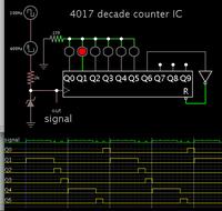
You can feed varying width pulses to a 4017 IC (decade counter). It rotates the pulses to each led in turn.


The simulation shows two led's getting longer pulses, hence they will be brighter than the others. By varying the pulse widths you can control each led brightness independently.

It is easy for this method to get out of sync. You may need to create a reset signal to maintain sync.
 

Sounds like a UART to me.

(usually) 8 parallel inputs -> 8 bit +framing bits on a single wire -> 8 parallel outputs.

You need three connections, ground, supply and data so you can use a standard stereo jack. You can either use a standard UART device (there are hundreds) which in most cases need to be set-up with various parameters so you may need some 'intelligence' by way of a microcontroller to make them work, or, you can use a microcontroller with a built in serial port. They cost about the same as a jack plug and socket but you do need to write a simple program (on a PC) which you then transfer to the microcontroller.
It's very easy to do.

Brian.
 
Re: Parallel > Serial > Parallel conversion

Sounds interesting.

Are we talking Arduino territory?

- - - Updated - - -

This might be a stupid question, but does it matter that the switches will be in a permanently high or low state as opposed to just pulsing?
 

I was thinking more of something much smaller and cheaper than Arduino. Just a single PIC, one capacitor and the switches at the sending end and a single PIC, one capacitor and a series resistor for each LEDs at the receiving end. The capacitors simply go across the PIC supply pins for stability.

Example, 16F628A costs ~1.50 (needed at both ends)
100nF capacitor costs ~0.10 (needed at both ends)
6 x 100R resistors for the LED outputs costs ~0.01 each (only needed at one end)

so excluding the switches, plugs & sockets, LEDs and 5V power source the total cost is < 4.00 in UK sterling.
The 16F628A has a built in serial port and pull-up resistors on it's inputs so you just wire the switches between the pins and ground. At the LED end you just add one resistor in line with each output to an LED. With a little simple but clever coding and a few extra components, you can expand it to as many as 15 LEDs.

Brian.
 
Good - now all I need to do is find a PIC programmer ;)

Seriously though, that looks very interesting.

I have also been doing extra random research - and I have stumbled across DAC's and Shift Registers.

I think DAC's are out, but the shift registers got me intrigued, could a PISO and a SIPO be used to save any programming?

And would I need to wire in transistors to protect the SIPO due to current?
 

Forget DACs, It is possible to send an analog voltage from one end and use it like a 'VU' meter on an amplifier at the other end but the circuitry is quite complicated and you will not be able to control the LEDs individually.

Shift registers can be used but there is a drawback - each 'shift' needs a clock pulse to make it happen and you also need to tell it whether to shift a '1' or a '0' so you need a clock and a data line as well as power and ground, that's four wires. There is an additional problem of synchronising the two ends, Shifting alone doesn't guarantee that a switch will operate the same LED each time because it may start in a 'mid shifted' state at power up. To fix that you need to reset both shift registers simultaneously, that's wire number 5!

The UART method gets around the problem by wrapping the data between a 'start bit' and a 'stop bit' of known polarity so the receiving end can detect the correct position of each data bit within the transfer, we call it 'Framing'. It allows you to send 8 bits, one per switch in a way that the receiving end can allocate the first bit to the first output pin and so on. In essence, what you put in comes out the same at the other end but the link in the middle is sending the switch states one after another along a single wire.

Don't worry about programming a simple PIC, it's really easy and the tools for writing programs and debugging them are free from the manufacturer. You will need something to transfer the finished program into the real IC but again that costs pennies to build yourself or you can buy a ready made programmer for very little.

Answering your earlier question, in it's simplest form, a program will replicate the exact state of the switches on the LEDs, there is no need to 'pulse' them but with a relatively large program memory space in those PICs you can adapt the program to do almost anything you want. The limit of applications is almost boundless, I have a 16F628A here that reads wireless ID cards, reports the number back to a central control box (also a PIC!) and if accepted it unlocks a security gate and if it's dark, also turns security lights on for 2 minutes. It even logs the time and card number and reports it on an LCD.

Brian.
 
SOLD :D

I'll look into the programming side of things another day, at least I'm on the right track now.

Is there anything like the 16F628A, but smaller?

Also, could you explain/confirm the way the 16F628A's are connected?

I am assuming the input chip is connected to VCC and GND and the switches go to 6 individual inputs (can you identify which pins, I have never dealt with IC's at this level and I am confused by the multiple terms against each pin). I presume the cap goes across VCC and GND? Or does it go across the output? Ignore that, I just re-read your previous post.

Similarly, I presume the output chip has the LED/Resistors wired to the same pins as the switches. Are the inputs on this the same as the outputs on the first chip (assuming they are crossed over). Again, having re-read, I am guessing there is only 1 data wire, plus VCC and GND.

And that's it? The second chip doesn't need anything else?
 
Last edited:

Having slept on it, and doing some research (which shows the smaller packages only have 6 GPIO (and I need 7)) it looks like this is the way to go.

Thank you very much for your help.

I have one more question.

Using 2 more inputs, I will be able to trigger 2 further events.

Depending on position, I want to toggle the Colour of the lamp and also the orientation of the pattern (rotate it 180°)

I think I can work out how to do that, but how do I save the state until it is reset by a new event? Seeing as the power will be dropped when the piece is disconnected.

Would a larger capacitor across VCC and GND in the receiving piece act as a power source to not lose the state?

I'm not worried about keeping the lamps lit when the piece is removed, just saving the colour/orientation state.
 

Re: Parallel &gt; Serial &gt; Parallel conversion

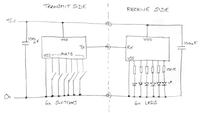
sorry fo the scribbled sketch!

You can use a smaller PIC but bear in mind it needs 6 pins for your switches/LEDs, one pin for transferring the data and two for supply and ground and as the Tx and RX pins are normally present at the same time, even if you are only using one of them at a time, you need a minimum of 10 pins. The next size up from 10 pins is a 14-pin package, smaller than the 18 pins on a 16F628 but not by a lot.

For simplicity, the switches should be wired to PORTB of most PICs, the reason being that there are internal 'pull-ups' on that port in all PICs. A pull-up ensures the pin goes to a high voltage (5V) state unless you pull the voltage down outside the IC. As the switches connect to ground, the pin will go between 5V and 0V depending on the switch position. You can use any other input pin available on the PIC but if it's one without the interal pull-up, you have to add an external resistor to do the same job. Without a pull-up, the pin would go between ground when the switch shorts is closed and an indeterminate state when the switch was opened, it could be interpreted by the software as high or low or even drifting between states randomly.

You can use any output pin to drive the LEDs, all PIC pins can produce enough current to operate small LEDs.

Brian.

- - - Updated - - -

Sorry, our last posts crossed over.
Using 2 more inputs, I will be able to trigger 2 further events.
You have space for about 2,000 instuctions inside the PIC, that's plenty to do almost anything you like with the data. Bear in mind what I said about other inputs needing external pull-up resistors.

Changing colour is slightly more complicated but not impossible. You can use 3 pin LEDs which have one common pin and one for each of the two LEDs inside the package, they give one, the other or both as colour options, typically red, green or both giving yellow. Or, you can use two pin LEDs which work by reversing the polarity across the wires, they can give the appearance of three colours if you rapidly swap the polarity but it's easier to threat them as one colour or the other.

I think I can work out how to do that, but how do I save the state until it is reset by a new event? Seeing as the power will be dropped when the piece is disconnected.

Easy, most PICs have non-volatile memory in them (aka EEPROM). It's a special area of memory that retains data (for many years!) even when the power is turned off. Your program would store the state of the LEDs in the memory each time it changed and when first powered up would retrieve the state and send it to the LEDs.

Trying to keep the power on by storing energy isn't a practical (or small) solution.

Brian.
 

Attachments

  • PIC_Tx_Rx.jpg
    PIC_Tx_Rx.jpg
    25.4 KB · Views: 109
Firstly, don't worry about the crossover - I was in the moderation queue.

Secondly, your sketch is fine - everything is there that I need to understand what you are saying.

Now I am beginning to get some sort of understanding about this, I can now expand out from what has currently been 1 face of 1 piece on 1 part of the playing field to the full shebang.

OK. Lets start with the playing pieces.

There are 5 pieces in total, 4 player pieces and 1 non-player piece.

Each piece has 4 faces, so that means 24 LED's per piece. Most of my patterns require for only 4 of 6 LED's to be lit, but I need to make sure that the unit is capable of powering all 6 (24) at once.

I'm struggling to understand the tech specs of the 16F628A in this respect.

The LED's I'm looking at are Kingbright L-59EGW

Red - Max V 2.5v, Typ V 2.0v, Max I 30mA
Green - Max V 2.5v, Typ V 2.2v, Max I 25mA

So I'm thinking with a 5v supply I can run the 4 LED's as 2 x 2 parallel/series, without any series resistors - if that makes sense. If I have that right, it should draw 5v 60mA Max per set of 4 LED's.

With all 6 (24) LED's lit, that equates to 300mA!

I am presuming I will need to add transistors to switch between the 2 colours.

Other than that, I think I am reasonably happy with how the pieces will be wired and just need to work out the programming.

Now for the complicated bit!!!!!

The board.

On the board there are 4 "Home" locations, 12 "In Play" locations and 16 switches.

The "Home" locations set all the LED's to off, and set the orientation and colour of the playing piece.

The "In Play" locations will only affect the LED pattern on the pieces.

Now as I see it I have 2 ways of wiring all this up.

I can supply a PIC for each individual "Home" and "In Play" location. This increases the number of parts and creates some slightly confusing wiring as each "In Play" location could be connected to up to 8 PIC's.

The other option is to get 1 large PIC. This would greatly simplify the wiring, but increase the programming complexity.

In total it would need 24 inputs (16 switches and 8 states (2 for each home location)) and 16 outputs (12 for each "In Play" location and 4 for the "Home" locations). That's a minimum of 38 pins (including +V and Gnd).
 

It is not clear whether you want to control six pieces independently, or control 6 led's in one piece?

You can feed varying width pulses to a 4017 IC (decade counter). It rotates the pulses to each led in turn.


The simulation shows two led's getting longer pulses, hence they will be brighter than the others. By varying the pulse widths you can control each led brightness independently.

It is easy for this method to get out of sync. You may need to create a reset signal to maintain sync.

This idea can work if you make the encoder and decoder to simulate a UART with Start/stop bits and 8 data bits.
THis can be done with pattern matching a SIPO shift register. Serial iN parallel out and some gates. Each port (LED would be hard wired to a separate bit to decode its state ON or off and a latched outputs in each frame at a 1kHz rate can be loaded by the encoder PISO register. THe data frame an be divided by two ( D FF Qnot to D input) to simulate a UART sending a byte every other millisecond. to sync each decoder.

The details require more time than I have.
 

You just made it a whole lot more complicated than your first query suggested!

Firstly the max I (maximum current) of the LEDs is the current at which the manufacturer will no longer guarantee they will not be damaged. For most purposes you should aim for a current well below the maximum. Think of 'max I' as being the red line on your engine revs, you may be able to go beyond it but then you might launch a piston into orbit.

You can not safely use LEDs like ordinary lamps. An incandescent lamp produces more heat and light as you apply more voltage across it, an LED does nothing up to a certain voltage then, if you let it, it burns out! You have to give them sufficient voltage to glow but also limit the current they pass to keep them from cooking. The resistor is there as the current limiter. You can join more than one LED in series, in which case you need more voltage but still have to limit the current, what you can't do reliably is wire them in parallel as manufacturing differences tend to make one hog more current than the other.

There is a trick you might want to consider, it's called 'mutiplexing' where you can drive many more LEDs from just a few output pins. It relies on there only being a few illuminated at any one time but your rapidly switch to another selection in sequence. Persistence of vision make it look as though they are all working at the same time. It can be used in your plans but is a little more difficult to implement.

Brian.
 
Right - had time to do some more research...

Multiplexing looks like a plausible solution. Looking to minimise connections and looking at the specs of the LED's and your previous comments I reckon I could get away with multiplex switching between 2 pairs of LED's in series on each output. Maybe as this is just alternating between 2 columns, with the rows taken care of by the output data, there could I could use 2 more pins on the GPIO to alternate between the columns, or one pin and a transistor or use the outputs of an independent Astable Multivibrator?

So taking 2 LED's at a time I think I would need the following resistors...

For the Red (2.0V Typ, 20mA Typ) = [5.0v - (2.0v + 2.0v)] / 20mA = 50R (nearest is 56R)
For the Green (2.2v Typ, 20mA Typ) = [5.0v - (2.2v + 2.2v) / 20mA = 30R (Nearest is 33R)

I would need to use one more out put to switch between red OR green, but not constantly.

What do you think?
 

Just, you don't need 20mA for the LEDs to be nice and bright, even 10mA should be more than ample - benefit of longer LED life and that of saving on power consumption of whole circuit.
 
Boom - back in the game...

All that talk of multiplexing threw me a little.

I've slept on it and done some rubber duck debugging (talking to myself as I drive along) and realised that even only using 1 LED per output, of any more than 1 was lot at a time they are in parallel.

Then I went back and looked at what I wrote (it's been a long time since I've played with circuits so I've forgotten a lot (and I didn't know a huge amount to begin with)). Thanks to d123's reply and some further research I've come to the conclusion I can run them in parallel.

Just, you don't need 20mA for the LEDs to be nice and bright, even 10mA should be more than ample - benefit of longer LED life and that of saving on power consumption of whole circuit.

I don't need them to be bright, just visible... Which means I can drop them to 5mA.

I could still run 2 together in series, but due to the physical layout it will actually make more sense to run them all individually.

This will mean 20mA total per output making a max of 120mA on the port if all 6 outputs are active.

That means, if my math is correct, that I will need 1 560 or 620 Ohm resistor per LED
 

d123: It would make the LEDs last longer - maybe 60 years instead of 50 !

If you want to individually control 24 LEDs the easier way is to arrange them in a 6 x 4 matrix. What you do is use a resistor per LED but instead of connecting them from the PIC output to ground, you wire the 'ground' side back to another PIC pin. So you have 6 outputs providing 5V to 6 LEDs on each side but the common return path for each side goes back to the PIC (or better still a transistor switch driven from the PIC). You rely on the common connection having to carry current from all/any of the LEDs on one side being enabled for any of those LEDs to light up. Then the software keeps 4 different bit patterns, one bit per LED per side and outputs the patterns in sequence while enabling the corresponding side switch.

So if we call the sides A,B,C and D, it makes the + side of side A LEDs high or low according to pattern A and at the same time enables the - side to pass current to ground, then it switches side A ground connection off and repeats the process for side B, then C then D then back to A. If you do it fast enough (> about 100Hz) the flicker can't be seen and it looks like each LED is on or off continuously.

Brian.
 

Looks like we crossed in the post again.

I'm not trying to control 24 LED's individually. I'm only trying to control 6 and replicate that result across a further 3 faces. You could say in trying to control 6 banks of 4 LED's - were the entire bank is either on our off, nothing rise.
 

Status
Not open for further replies.

Part and Inventory Search

Welcome to EDABoard.com

Sponsor

Back
Top