Continue to Site

Welcome to EDAboard.com

Welcome to our site! EDAboard.com is an international Electronics Discussion Forum focused on EDA software, circuits, schematics, books, theory, papers, asic, pld, 8051, DSP, Network, RF, Analog Design, PCB, Service Manuals... and a whole lot more! To participate you need to register. Registration is free. Click here to register now.

Parallel platea capacitor

dhiaa12

Newbie level 5
Newbie level 5
Joined
Aug 25, 2024
Messages
8
Helped
0
Reputation
0
Reaction score
0
Trophy points
1
Activity points
61
Hello dears,
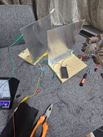
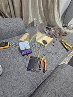
Its really confusing, one guy demonstrated in video am attaching; he demonstrated how voltage of parallel plates capacitor changes when he changes distance between plates, area and dielectric.
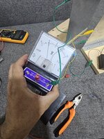
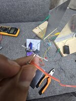
I have tried same experiement with same tools that he have, but I failed. The capacitor similar to mine should be around 80 pf ( Aluminum 20 cm × 20 cm in dimensions ) and I think after he charge it and disconnect it from power supply, he should gets zero voltage as I get ! Due to small capacitance and charge should leak quickly.
is he doing something I can't understand??
How he gets voltages on plates after disconnecting the capacitor?
Any ideas?

 
From a website I imitated a similar experiment by rolling several square inches of aluminum foil between sheets of paper. The value was about 1nF which I discovered as I built it into a simple oscillator. (1nF about matched the value achieved by the website experimenter.) I didn't test how long it could maintain a charge when disconnected.

After all my DMM is 1MΩ input resistance. It drains 1nF of its charge in a few mSec. Isn't a more sophisticated instrument needed to measure 80pF? I think so.
Yes Dear Brad, confusing!
Might be he connected beneath the plates electrolytic or Ceramic capacitor? If he did so, and it worked in some way ,how come voltage changes when he reduced the opposite area of plates ??
THis is beyond my mind thinking!
 
A low leakage test method must be used.

The theory is for parallel plates with a gap, x is much smaller than width, w then C [pF] drops linearly with x such that C*x = constant.

We know charge must be constant with no loss so Q=CV and as thus V increases with the gap or V*x = constant.
 
A low leakage test method must be used.

The theory is for parallel plates with a gap, x is much smaller than width, w then C [pF] drops linearly with x such that C*x = constant.

We know charge must be constant with no loss so Q=CV and as thus V increases with the gap or V*x = constant.
If we speak in theory, what you said is valid.
In the video is different story. I have same parallel plates and voltimeter but I can't be able to get any voltage after disconecting the capacitor from power supply.

How come small pf capacitor retain voltage ?
I just think might be some trick !
 
This is the other demonstration of changing the distance of plates and how effects the voltage
 

Attachments

  • Jawad Hamed_ profile picture - 1180417149958763(720p).mp4
    4 MB
Think about what I said and what is Tau=RC of your test method

He really did not demonstrate anything useful. Just a lot of hand waving..
I must have been FET buffered meter, with >10 Gohm not your DMM with 10 Meg.


10pF * 10Meg = 100 us.
 
the test is better done with a spark gap - as you increase the distance between the plates ( assuming they are charged beforehand ) the volts go up and a spark will ensue - about 1kV / mm in dry air - you may need a dark room
Any leakage or dampness in the air ( e.g. humidity > 30% ) will drain the charge away.
C = Q/V , as C goes down ( increased distance ) V must go up if no charge is leaking away . . .
 
Might be he connected beneath the plates electrolytic or Ceramic capacitor?
In fact he may have an FET-VOM with internal impedance which takes a longer time to discharge a small cap.

As for hooking up an additional capacitor, he might do this to ensure his circuit is working as he starts the experiment. A tiny value is enough to tell him he's on track. Suppose it's 100pF. Then he moves his plates which average 80pF. That has a big influence on the overall value. It tells him his demonstration is succeeding. Then he can configure a circuit to send the meter reading up or send it down as he moves the plates.

See the gloves in his hands? I believe he's working with high voltage in order to make his demonstration succeed.
 
Hi,

My guess: the whole video is fake.
* the voltmeter already shows voltage .. even if not connected
* the voltmeter changes voltage when he shifts the plates .. but does not change when he (accidentally) changes the distance

I guess he used some linear potentiometer when shifting the plates.

****
We know charge must be constant with no loss so Q=CV and as thus V increases with the gap or V*x = constant.
Energy needs to be constant. One can not "create" energy.
This also applies for the capacitor.
But on a charged plate capacitor there is mechanical force between the plates they attract each other.
When moving the plates apart one needs to "work" against this force. In other words one needs to introduce energy.
If I´m not mistaken, this mechanical energy also adds to the stored "capacitive" energy.

How much this is ... I have no feel...

And for sure this is more obvious when we change the distance of the plates (then force vector and movement vector are in the same direction)
But I think similar effect takes place when shifting the plates (to change the area), it is just reduced.

*****
Also:
With 80pF ... one surely has to consider all the parasitic additional capacitances of the wires, the hands (with their relatively big area) and the stray capacitances inside the meter. These (constant as well as not constant) capacitances are all in parallel with the plates. And need to be considered, if one wants to calculate the voltage change.

*****
In physics class we used an "electrostatic voltmeter". No coil and no amplifier involved. It just uses the force between two charged plates to create a movement of an indicator.
As far as I rememer it worked for high voltages only and had no scale. So it was no accurate measurement ... but it was rather lossless

Klaus
 
Thank you guys for the helpful disscussions.
I will consider using buffer FET, like JFET 2N5457 and see how it works .
will feed back to you soon, to share experience .
 
Hello Dears,
I have tried with JFET 2N5457 and it failed.
Voltage reading drops to zero directly.
I have no idea why ? Do you suggest me something?
appreciate your ideas!
 

Attachments

  • 20240905_231724.jpg
    20240905_231724.jpg
    3.4 MB · Views: 7
  • 20240905_231723.jpg
    20240905_231723.jpg
    3.2 MB · Views: 7
  • 20240905_231719.jpg
    20240905_231719.jpg
    3.1 MB · Views: 7
  • 20240905_231713.jpg
    20240905_231713.jpg
    3 MB · Views: 6
  • 20240905_231649.jpg
    20240905_231649.jpg
    4.2 MB · Views: 7
Hi,

information: I see here 13MB of photos. That simply could be reduced to less than 1MB without losing thread related informations.
I don´t download this huge data. There are tools in your camera, PC, laptop, cell phone and even online to reduce picture data size.

Klaus
 

LaTeX Commands Quick-Menu:

Part and Inventory Search

Welcome to EDABoard.com

Sponsor

Back
Top