Continue to Site

Welcome to EDAboard.com

Welcome to our site! EDAboard.com is an international Electronics Discussion Forum focused on EDA software, circuits, schematics, books, theory, papers, asic, pld, 8051, DSP, Network, RF, Analog Design, PCB, Service Manuals... and a whole lot more! To participate you need to register. Registration is free. Click here to register now.

Output of LM317 is gradually decreasing

Status
Not open for further replies.

rajaram04

Advanced Member level 3
Joined
Jun 17, 2012
Messages
871
Helped
6
Reputation
12
Reaction score
5
Trophy points
1,298
Location
earth
Activity points
7,687
Hello sir

i am using LM317 as voltage regulator to get a 9 volts o/p & at the I/p i am applying 18 volt dc out from a bridge rectifier

I followed all type of diagrams available all around but the output level is going down (with no load & too load condition)

the whole assembly is on bread board

please help me in solving the issue
 

Hello sir

Hi rajaram04

How you are so sure that only sirs will try to answer you ? ha ha ( of course i'm male but sometimes girls will try to answer here so use a common word rather than that like hi all )

Anyway ,

i am using LM317 as voltage regulator to get a 9 volts o/p & at the I/p i am applying 18 volt dc out from a bridge rectifier

I followed all type of diagrams available all around but the output level is going down (with no load & too load condition)

the whole assembly is on bread board

please help me in solving the issue
May you attach the schematic which you have built ? it is pretty hard to answer without any kind of schematic .
But i guess you built it wrongly perhaps you maybe your capacitors are dealing with problem or if all of em ar right probable your IC is came from china !

Best Wishes
Goldsmith
 
Hi rajaram04

How you are so sure that only sirs will try to answer you ? ha ha ( of course i'm male but sometimes girls will try to answer here so use a common word rather than that like hi all )

Anyway ,


May you attach the schematic which you have built ? it is pretty hard to answer without any kind of schematic .
But i guess you built it wrongly perhaps you maybe your capacitors are dealing with problem or if all of em ar right probable your IC is came from china !

Best Wishes
Goldsmith


hahaha ya ya Thanks SIR its a "word of honour" actually i am using as 've no idea about girls here & too i've never seen any girl taking intrest in such things :p specially electronics , since 2012 i discussed with males (as per profile info.) only , may be . . i am wrong

Well well well jokes apart , i guess too that its a part of china made
& firstly i applied simplest configuration ever but later i did these :

**broken link removed**

& the variations i made here is

> at output i applied 1000 mfd cap. (max.value)
> pot. value is of 2k value
> diode value is 1N4007
> R1 value is 220 E

Now,suppose at the begning if the output reading shows 9.05 or a lil.bit more , then later it gradually reaches the level of 8.90 or 8.75 or less & is enough to distract my experiments :(
 
Last edited:

Your attachment does not work. It does not show a schematic or anything.

The voltage drops up to 3.3% which is too much for a good voltage regulator IC.
Which company made the LM317 IC? Did you try a replacement?
Did you try a 220 ohm resistor from a different manufacturer?
Did you try replacing the pot with two fixed resistors in parallel to make 1364 ohms?
 
A very common reason for the voltage output dropping on a regulator is because it is overheating, and the regulator protects itself.

Have you checked the case temperature, even with your finger? If the case feels uncomfortable hot, most likely the regulator is going into thermal shutdown.
Add a larger heatsink, properly torqued down and with thermal grease.
 
He said the voltage dropped even when the LM317 had no load so it was not getting too hot.

You are absolutely correct, but the "finger test" takes no more than two seconds to do.

And...this is important...........the original poster has not provided neither a schematic nor an image. There could be some "hidden load".
You and I have browsed thru these forums for many years. How many times, when queried further, has the original poster come back with a crucial piece of information.
Something like: "By the way, the circuit is fully unloaded, save by a small, 500 mA light bulb..." Or something along these lines.

I'm not saying this is the case here. But as Goldsmith mentioned today in another post: "We are not Ray Charles", which I think it is both hilarious and accurately describes many of the requests for help in this forum.
 
Maybe he made his own resistors with pencil lead or something. Remember "carbon composition" resistors that changed their value if you looked at them?
 
Maybe he made his own resistors with pencil lead or something. Remember "carbon composition" resistors that changed their value if you looked at them?

Yes, I remember them......

With 1/2 watt or larger carbon comp resistors, one could actually trim the value with a triangular file. One would file and measure, file and measure, file and measure, until one got the required resistance.

The do the same with SMT precision resistors nowadays, but they use a laser to trim the film.
 
Maybe he made his own resistors with pencil lead or something. Remember "carbon composition" resistors that changed their value if you looked at them?


woa woa woa discussions are waving musically :p

First of all i am not using other components other than electronics cause thats a part of my other experiments where i applied pencil carbon heavily sketched on a paper so as to act as a variable resistor for an astable multivibrator just to generate typical sound samples :D

But here as per audioguru in post #4 i applied all the three steps.
i replaced the devices with other company model but the issue was stu.
Afterwards i gone through the 3rd step in which he said to replace pot with pair of resistor & finally the problem was sorted out & the system is working absolutelyyyyyyyyy correct

Too ya its true that with no load condition i had problem of voltage fall
& reagrding thermal agitation , here with full load its still generating a very lil.amount of heat not enough to sence even . . so with no load mmmmmmmmmm hmmm . .

thanks to all :)
 

So it was the pot that changed its resistance that slowly reduced the voltage.

The datasheet for the expensive LM117 and less expensive LM317 says that the output voltage will rise for some of them without a load if the current in R1 is less than 5mA for the LM117 or 10mA for the LM317. The resistor has 1.25V across it so the maximum value for an LM317 is 1.25V/10mA= 125 ohms, use 120 ohms. You can use 220 ohms with an LM117.


hmm ya as per your explanations atlast i am replacing 220 ohms with 120 . . . now its all going good . . but the output is varrying between 9.05 & 9.06 v . . . . . . . . .
too whats the reason of variation due to pot. ? ? ?
 
Last edited:

So it was the pot that changed its resistance that slowly reduced the voltage.

The datasheet for the expensive LM117 and less expensive LM317 says that the output voltage will rise for some of them without a load if the current in R1 is less than 5mA for the LM117 or 10mA for the LM317. The resistor has 1.25V across it so the maximum value for an LM317 is 1.25V/10mA= 125 ohms, use 120 ohms. You can use 220 ohms with an LM117.


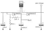
sir here is the diagram i am talking about , please check

lm 317 sample 00 copy.jpg

now what to do next for current regulation ??????????
 

You have capacitors and diodes that are not needed for a charger voltage regulator.
The datasheet for the LM317 has a simple current regulator circuit.
 

Attachments

  • LM317 current and voltage regulators for charger.png
    LM317 current and voltage regulators for charger.png
    98.1 KB · Views: 213
You have capacitors and diodes that are not needed for a charger voltage regulator.
The datasheet for the LM317 has a simple current regulator circuit.


ooooooo i see
i was thinking too about two LM317 after all your suggestion & here i got same

well as you explained about no need of diode & capacitor,i agree with the terms but without these applied components the output of voltage regulator is varrying too too much . .

so after going through many ckt.diagrams i connected all.

well first let me apply the above one

Too , here i need three LM317 as the current regulator needs 9.65 volts first . .

Sir in current regulator you marked 1.2 as R1 & 2W too
so is it 1.2k ?
&
Is the same power rate of 2W required ????
 
Last edited:

The datasheet for the LM317 shows that if the input to output voltage is at least 3V and the input voltage varies 10V then the output voltage typically varies only 1mV. It is called Line Regulation.
The datasheet explains that the Line Regulation is much worse if the resistor connected to the output pin has series wiring and/or the series resistance of a breadboard contact which is probably your regulation problem.

You do not need the third regulator because the MINIMUM INPUT (do you know what this is?) voltage for the current regulator is +9.65V. Use +12V to make sure that the input never goes below 9.65V.
Maybe the smoothing capacitor value of the bridge rectifier is too low and causes the voltage to drop too low 100 times per second. Here is a sketch of the waveforms from a bridge rectifier and if the smoothing capacitor value is too low then the voltage can drop to zero volts.

I explained in your personal message that the 1A current regulator always has 1.2V to 1.25V across the resistor from the Output to the Adj pin. The resistor value is 1.25V/1A= 1.25 ohms.
It heats with 1.25v x 1A= 1.25W so a 1W resistor will burn away. Use a 2W resistor that will not get too hot.
 

Attachments

  • bridge rectifier waveforms.png
    bridge rectifier waveforms.png
    18.5 KB · Views: 180
The datasheet for the LM317 shows that if the input to output voltage is at least 3V and the input voltage varies 10V then the output voltage typically varies only 1mV. It is called Line Regulation.
The datasheet explains that the Line Regulation is much worse if the resistor connected to the output pin has series wiring and/or the series resistance of a breadboard contact which is probably your regulation problem.

You do not need the third regulator because the MINIMUM INPUT (do you know what this is?) voltage for the current regulator is +9.65V. Use +12V to make sure that the input never goes below 9.65V.
Maybe the smoothing capacitor value of the bridge rectifier is too low and causes the voltage to drop too low 100 times per second. Here is a sketch of the waveforms from a bridge rectifier and if the smoothing capacitor value is too low then the voltage can drop to zero volts.

I explained in your personal message that the 1A current regulator always has 1.2V to 1.25V across the resistor from the Output to the Adj pin. The resistor value is 1.25V/1A= 1.25 ohms.
It heats with 1.25v x 1A= 1.25W so a 1W resistor will burn away. Use a 2W resistor that will not get too hot.


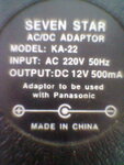
sir i am using 12 volts 500mA adapter
Model : KA-22
& is used for a panasonic cordless phone unit battery charger
here is snapshot image of parameteric label

Image0768.jpg

but in open circuit condition the output of adapter is showing 18 to 20 volts

is that all ok ?
 

The cheap power supply is unregulated. Its transformer has resistance that reduces its output voltage. It is made so that the voltage is 12.0VDC when its load draws 500mA. Then it is normal for its voltage to be higher with no load.
 
Status
Not open for further replies.

Part and Inventory Search

Welcome to EDABoard.com

Sponsor

Back
Top