Arilson
Newbie

- Joined
- Dec 15, 2024
- Messages
- 1
- Helped
- 0
- Reputation
- 0
- Reaction score
- 0
- Trophy points
- 1
- Activity points
- 6
Hello everyone!
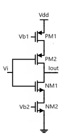
I believe this structure corresponds to an inverting amplifier known as a push-pull, but I am unsure about the role of PM1 and NM2. I think they act solely as a current-source load; is that correct? Would the total impedance seen at the output node be equal to (roPM1 + roPM2) || (roNM1 + roNM2)?
I believe this structure corresponds to an inverting amplifier known as a push-pull, but I am unsure about the role of PM1 and NM2. I think they act solely as a current-source load; is that correct? Would the total impedance seen at the output node be equal to (roPM1 + roPM2) || (roNM1 + roNM2)?
