Continue to Site

Welcome to EDAboard.com

Welcome to our site! EDAboard.com is an international Electronics Discussion Forum focused on EDA software, circuits, schematics, books, theory, papers, asic, pld, 8051, DSP, Network, RF, Analog Design, PCB, Service Manuals... and a whole lot more! To participate you need to register. Registration is free. Click here to register now.

Oscillator oscillation amplitude

Status
Not open for further replies.

I14R10

Full Member level 3
Joined
May 31, 2015
Messages
185
Helped
0
Reputation
0
Reaction score
0
Trophy points
1,296
Activity points
2,750
I tried searching and asking questions on few forums, but I didn't get an answer. Simple question

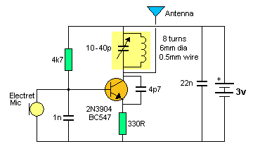
In oscillators, like this one


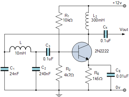
what is the amplitude of oscillations at collector? LTSpice simulation shows that it's almost rail to rail, but I would like to know what is the case in real life? Are oscillations really rail to rail?
 

Detailed analysis required. In the present circuit, oscillation magnitude is about 4 to 20 V, considerably above positive rail.
 

OK, then I have one more question. If I would want to amplify the oscillations and then send them to the antenna, should I use few stages of common collector buffer amplifiers? Since I have large enough voltage from the oscillator, for more power (range) I just need more current. I am talking about a single power source, of course if I want larger voltage I could use higher Vcc.
 

That depends on the antenna imedance. It will resonate at about 10.8KHz so the antenna would be huge!

Brian.
 

This is just an example circuit. Just imagine tank circuit that would oscillate at 100MHz.
 

In most countries it is illegal to transmit and cause interference to broadcast stations (100MHz is in the middle of the FM broadcast band) and the harmonics of your simple circuit causing interference to aircraft, police and ambulance communications.
 

I know that. I am working with really low power, 5-10mW. It has range of 50m maximum. I am a ham and I am well aware of what is not allowed. I don't remember exactly, but I think anything below 100mW is allowed for experimenting. Besides, this is more of a theoretical question. The only reason I am asking is because I want to make my own amateur radio transmitter eventually. And you don't have to mention how it can't be used unless it has passed technical inspection and if its harmonics are low enough. I am well aware of that too.

Sorry if this sounded too agressive, but I know what I am doing and that I can cause interference. But I assure you that I am using tuned amplifiers and band pass filters although I am working with this low power.
 
Last edited:

I made a simple low power FM transmitter that sounds great. I didn't design it but instead I fixed one that appeared on a forum and didn't work. My FM band is almost full of stations so I used the frequency of a weak foreign language station that is on the other side of my city.

The original circuit had its audio preamp transistor biased so that it was saturated when the 9V battery was new and the transistor was cutoff when the battery run down a little, and the sound was very muffled. So I biased the transistor correctly and added a low dropout 5V regulator. I fixed the sound by adding pre-emphasis of high audio frequencies like all FM radio stations have.
The oscillator frequency changed as the battery voltage ran down so I fed it from the voltage regulator.
The oscillator frequency also changed when something moved towards or away from the antenna so I added an RF amplifier transistor to separate the oscillator from the antenna.

Its range is across the street to an FM "radio" from The Dollar Store, down the street to a cheap clock radio and 2km across a huge river valley to my home stereo or my car radio.

I used it for less than one hour. Somebody on a forum said they also live in my city and made my FM transmitter, then he saw the RF cops go past with a huge antenna on the roof of their car. I think they were looking for me.

The RF cops caught me when I was a kid. I made a fan and its sparking brushes caused a lot of interference to many radios and TVs.
 

Attachments

  • FM tx mod4 pic and schematic.jpg
    FM tx mod4 pic and schematic.jpg
    196 KB · Views: 85

I made FM transmitter too. it had range of about 300m. I never use it. I made it just to see if I can. 2km is a lot of range. As I said, the oscillator and amplifier that I built doesn't have even 50m range. With all that said, I live in very remote area with first neighbor 100m away and next 300m away. On other side first neighbor is 100m and next one is 500m away. All around us is forest for 50km until first city. I know that short wave can propagate a long distance with small power, but I am not building shortwave oscillators. I checked on my ham radio, there are no interference on HF bands. Anything above 100MHz, if I can't hear it, nobody can.
 

I don't remember exactly, but I think anything below 100mW is allowed for experimenting.
You may be right but 100mW seems like quite high power for experimenting on unlicensed frequencies. I would have expected 100uW (0.1mW) more realistic.

Brian.
 

Maybe. Consider that at 145MHz (2m band) 5W with ground plane antenna barely gets you 50km range, 0.1W is not a lot. On the other hand, 5W at 7MHz gets you a lot more range.
 

Your best bet is to get yourself a 433 Mhz surface acoustic wave resonator, plenty of choices of frequency, and its on the Ham band, so you can run really decent power (if you do have a ham ticket). These resonators are very stable in frequency, so no worries there.

https://www.ebay.com.au/sch/i.html?...aw+resonator.TRS0&_nkw=saw+resonator&_sacat=0

Lots of circuits around on the internet for remote control transmitters on this frequency using these resonators.
 

Why do you think the range of my FM transmitter is only across the street and is as far as 2km? What changed the distance?
You did not show a schematic for your radio transmitter with a range of only 50m, instead you showed an audio oscillator. How sensitive is the radio that received the signal from your transmitter? Were the transmit and receive antennas the correct length and were they parallel to each other?
 

There were probably some obstacles and buildings that obstructed the signal. 2km was line of sight range. The schematics for transmitter that I was talking about is this


I had portable radio receiver that had its own antenna. Antenna on transmitter was cut at approximately the length it should be. I agree that if somebody was close enough with sensitive receiver they could hear it. Just how small range do you think it should be? 30m range doesn't even clear my property. I don't approve transmitting with high power, interfering with stations that are on those frequencies, but for such small power and short range, there is no way I'm interfering with somebody.
 

Just putting your hand anywhere near the antenna is going to cause a massive change in oscillation frequency.

Its going to be a real challenge at the receiving end.
The whole thing is just unworkable.
If you are actually going to do this and expect reasonable results, either a quartz crystal or a surface acoustic wave resonator is an absolute necessity to keep it on frequency.
 
Don't worry. I know that would be the case so I put a simple FET buffer between the antenna and oscillator.
 

Status
Not open for further replies.

Similar threads

Part and Inventory Search

Welcome to EDABoard.com

Sponsor

Back
Top